SudarshanK, DarkhanT
We introduced two Pcal lines at 240 Hz and 310 Hz on photon calibrator at Y end. The Pcal lines are about a factor of 10 above the DARM sensitivity at those frequencies. We will look into any changes in the amplitude and phase of these lines to determine the the position of cavity pole frequency. The cavity-pole has been observed at frequencies listed in alog LHO #18360.
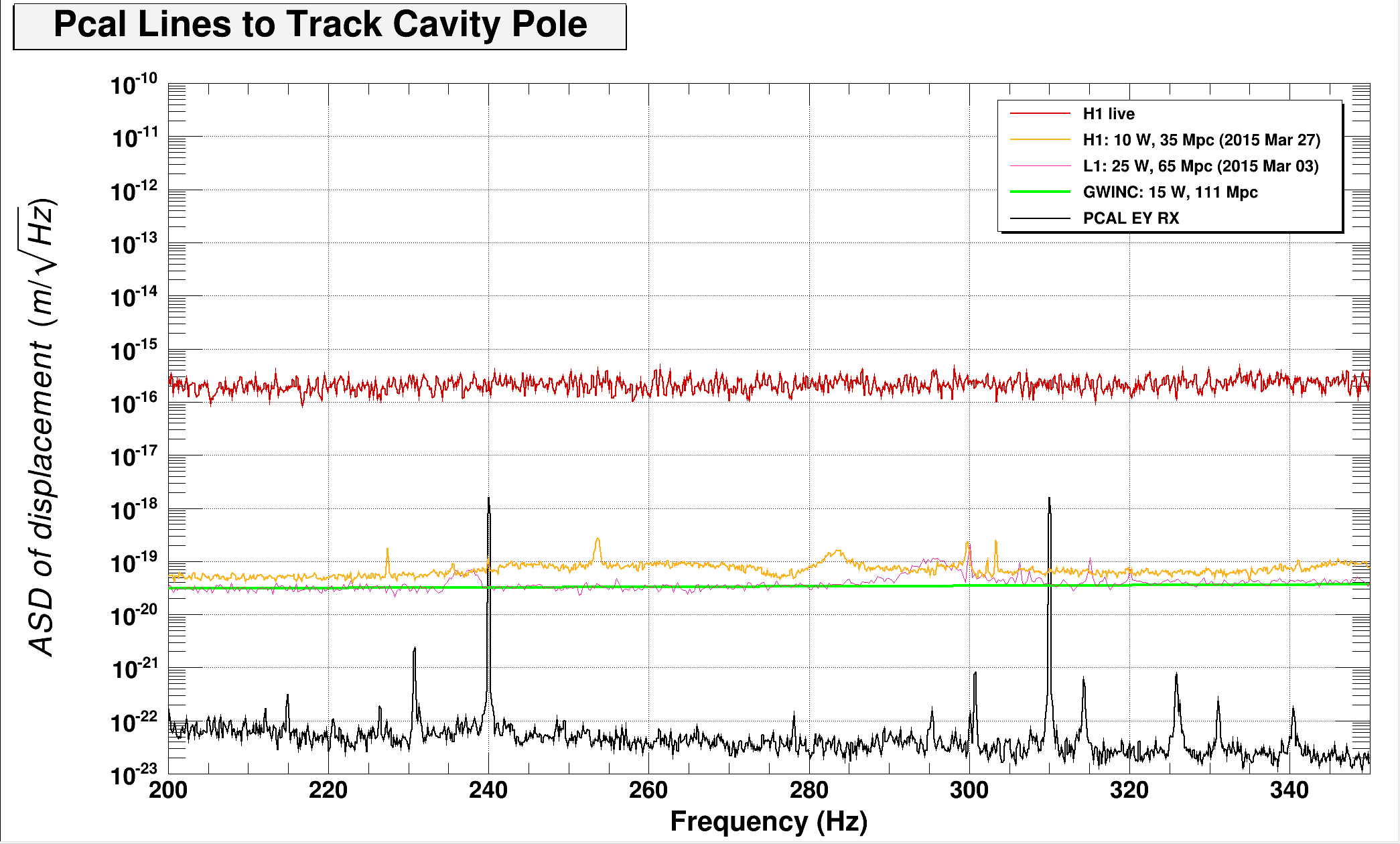
Since the pole frequency is at about 300 Hz, it would be useful to have a high frequency line, for example at about 1 kHz. This will allow a better reconstruction of the pole frequency.
If you haven't already, I recommend also putting a notch in the DARM loop at 310 Hz. That way any phase change that occurs at 310 Hz in DARM should be a direct measurement of changes in the sensing phase (which would presumably come from a chang in cavity pole). I probably would have gone a little higher with the 2nd line, closer to 400 Hz. Why did you choose what you did?
Gabriele, We also have a permanent Pcal line at around 540 Hz. We thought it should be enough. Is there any advantage of going close to1 KHz?
Peter, I will have to talk to Jeff about putting a notch on the DARM loop, I am not sure how to go about it. Regarding the choice of 240 Hz and 310 Hz, knowing we already had one line at around 540 Hz we picked a pair of line between one of the non-vetoed frequency band of pulsars. We could easily shift the second line to 400 Hz.
Larry Price did an analysis of just this situation, i.e. at what frequencies should you measure the transfer function to most optimally extract the features in the frequency response. His analysis showed that the most optimal place is at the feature itself. In other words, the best place to put your calibration line to most efficiently measure the cavity pole is at the expected cavity pole frequency. See: LIGO-G1400084
In light of this optimal, Fisher-matrix-based approach, Kiwamu and I have installed a notch in DARM at 322.1 Hz (actually an 80 dB elliptic bandstop from 321 Hz to 323 Hz). The goal is to inject a calibration line digitally into DARM control, so that we can use an LSC lock-in to demodulate the line.
We have set up LSC oscillator #3 to take OMC DC and demodulate it at 322 Hz. Both I and Q have 4th order butterworth low-pass filters. The lock-in output drives ETMX and ETMY differentially. The lock-in drive is currently 0 ct. It has not been set yet.
Better check the assumptions here. Doesn't Larry's result assume an open-loop measurement, white actuator strength, and white measurement noise (none of which holds in this case)?
Chris,
Thank you for pointing it out. We also noticed that the assumptions were not quite valid in our case. On the other hand, Larry's analysis still gives us a good idea of what frequency we should excite. According to his Fisher matrix analysis, the measured transfer coefficient exhibits a maximum response to change in the cavity pole frequency when the excitation is at the exact pole frequency. This led us to a frequency at around 322 Hz. If you take the spectral shape of sensor noise (or DARM residual) and the actuator transfer function into account, probably a slight lower frequency than the current choice may be better, but since we wanted to have a notch in DARM far from the UGF, we chose it to be close to the cavity pole.