Reports until 20:03, Wednesday 07 December 2011
H2 SUS
rich.abbott@LIGO.ORG - posted 20:03, Wednesday 07 December 2011 - last comment - 12:35, Thursday 08 December 2011(1858)
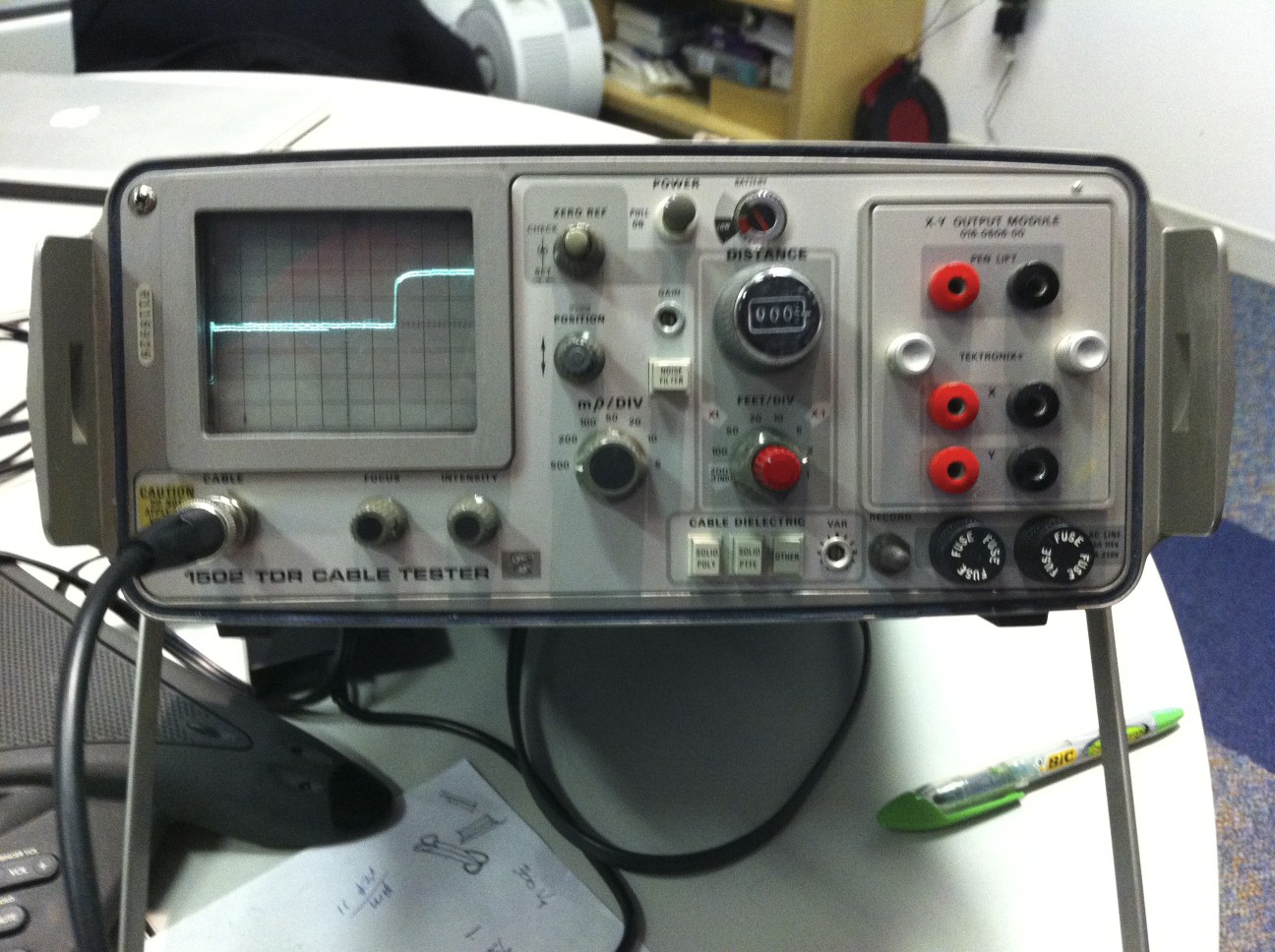
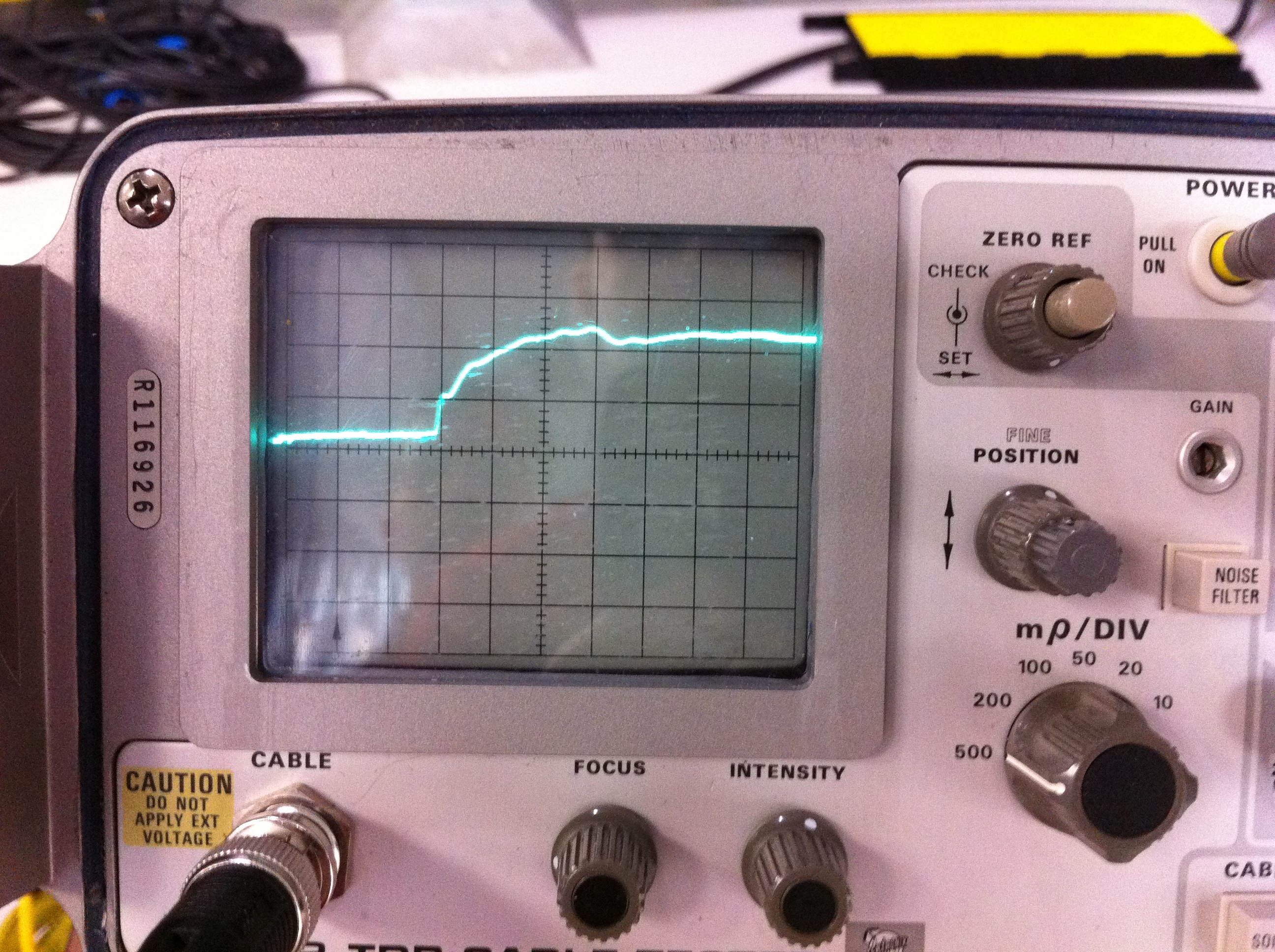
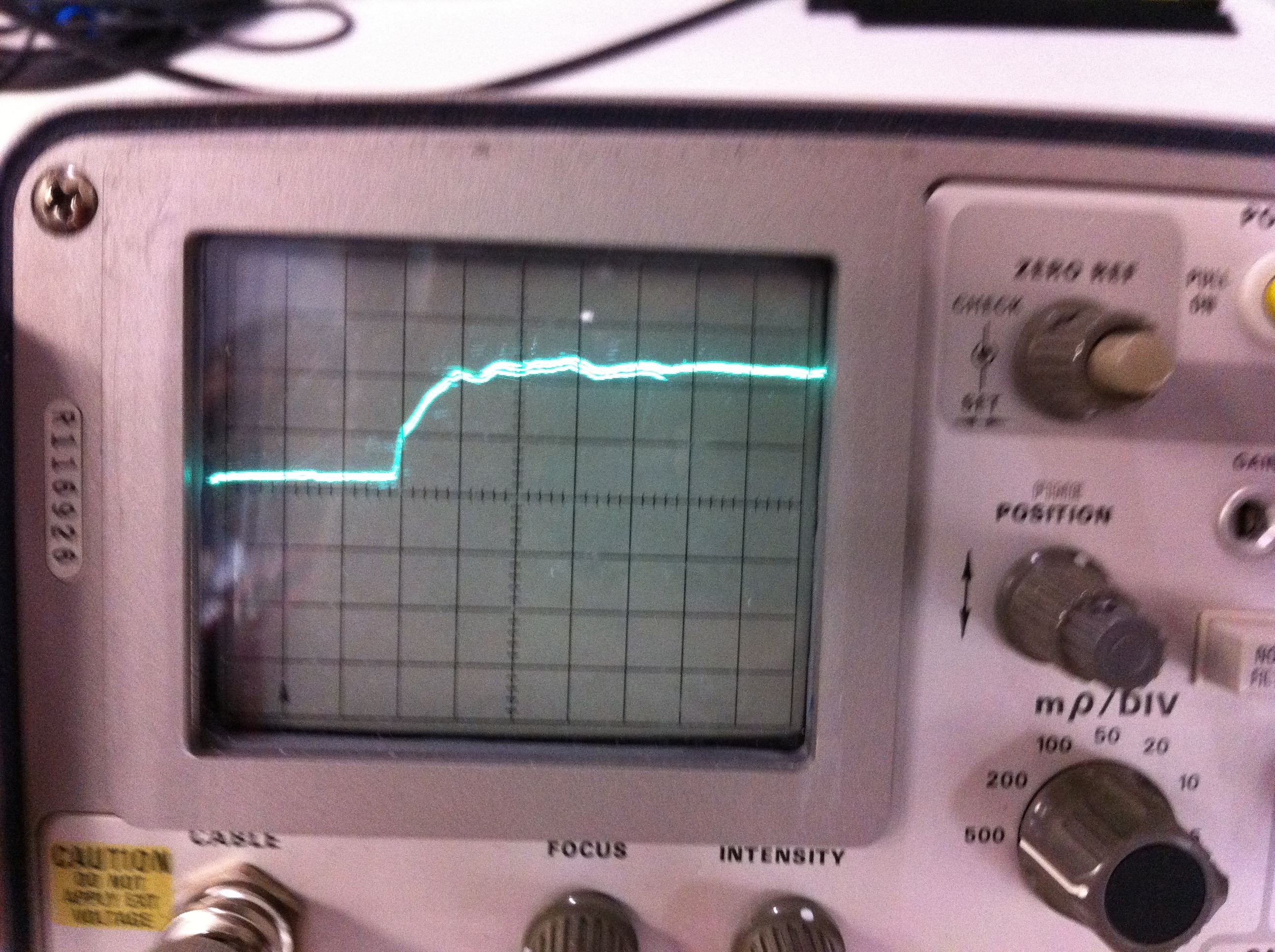
Test of ESD Cableing Integrity
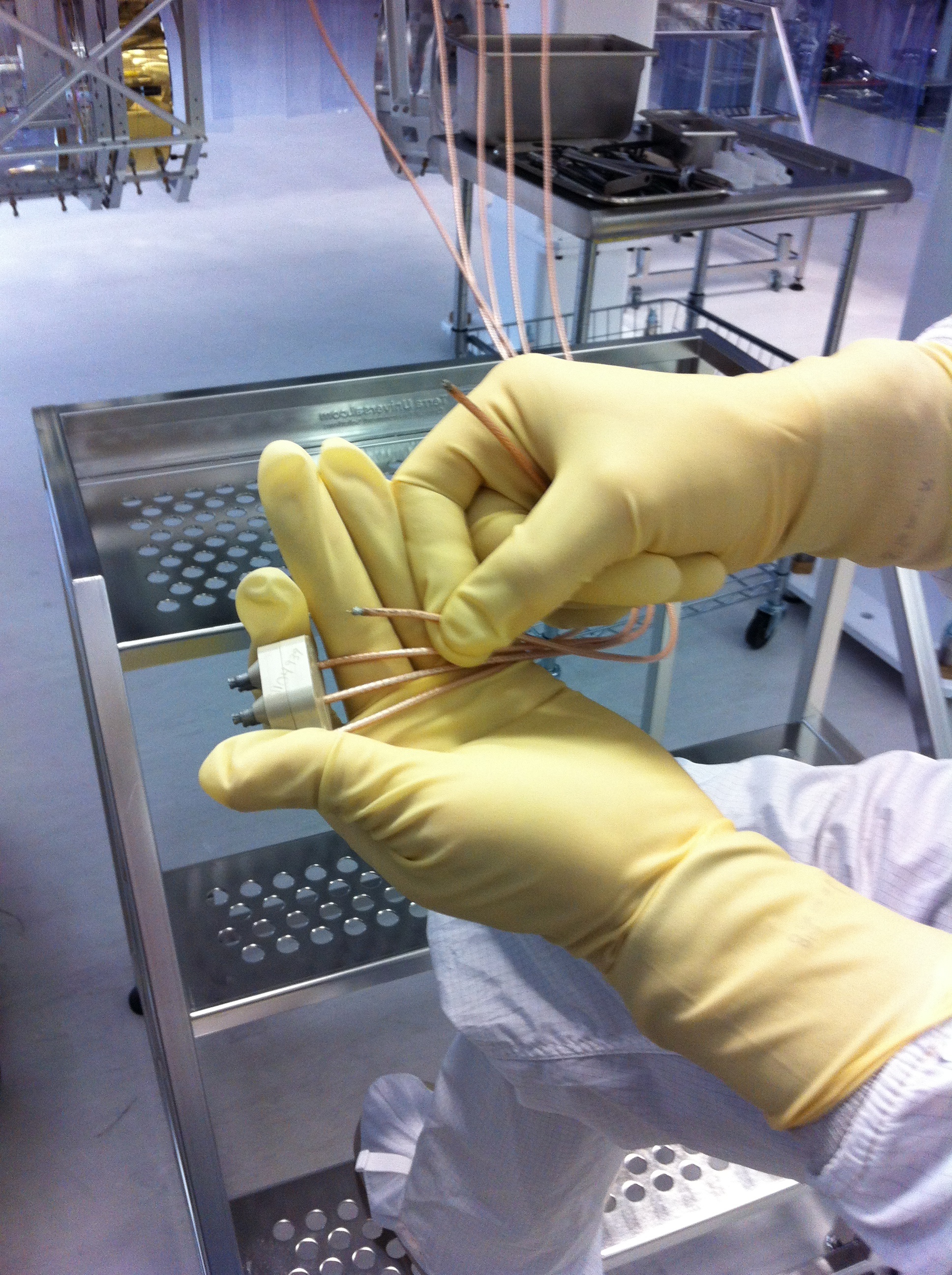
Performed a test of the ESD cabling associated with the BSC8 cartridge.  A time domain reflectometer was used to verify the integrity of the coaxial cable from the vacuum side connector down the suspension chain leading finally to the reaction mass ESD actuator.  Discovered that 3 out of the 5 coaxial paths were bad.  Cause traced to a failure of the solder joints used to attach the coaxial cable to the PEEK custom connector.  The joints were baked at 200 degrees C in the vacuum bake process.  The solder used has a melting temperature of 184 degrees C, which resulted in a complete failure of these connections.  Even the two that tested good rapidly failed when tension was applied to the connections.

After a conversation with John Worden and Mike Landry, we elected to leave the majority of the cabling intact and to re-terminate the coaxial cables in a new connector after the cartridge is installed.  The 5 coaxial cables will be drawn through the aperture of the conflat feedthrough and a new connector will be installed in situ.

All of the five cables appear intact and correct aside from the failure of the vacuum side conflat mate.
Comments related to this report
mark.barton@LIGO.ORG - 09:39, Thursday 08 December 2011 (1864)
For reference, here are some pictures of Rich's setup:

 1. The front panel of the TDR (time domain reflectometer) box used by Rich. This particular unit is very old and failing, and a modern replacement is being procured, but the new one will be similar in concept. The screen shows the output for a 15' test cable with an open circuit termination. The horizontal scale is set to 2" per major division, and a fairly clean reflection from the end of the cable can be seen. (A short circuit would have given a reflection of opposite sign, and a impedance-matched termination would have given little or no reflection.)

2. The output for channel 1 of the ESD (viewing the connector as a boat shape and counting left-right, top-bottom). The horizontal scale is now 5' per division and the horizontal position has been set to put the section of the trace representing the 15' of test cable on the outside of the vacuum flange offscreen to the left, so that the visible portion represents only the in-vacuum cable. There is a more complicated shape reflecting the different impedances of the conductors in the chain and the capacitance of the electrodes at the end.

3. The output for channel 3 of the ESD. It is quite similar to ESD 1. These traces can serve as a provisional reference for what a working channel should look like. (There may be slight differences when the connector is repaired, and/or the TDR is replaced.)

4. The connector falling apart in Hugh's hands. There is supposed to be a gold pin on the end of each inner conductor, but the solder has melted and several of the pins have come off.

Mark B.
Images attached to this comment
mark.barton@LIGO.ORG - 12:35, Thursday 08 December 2011 (1867)
Rich spotted a typo in my earlier comment: the horizontal scale in the first picture is 2' (feet) not 2" (inches) per division.