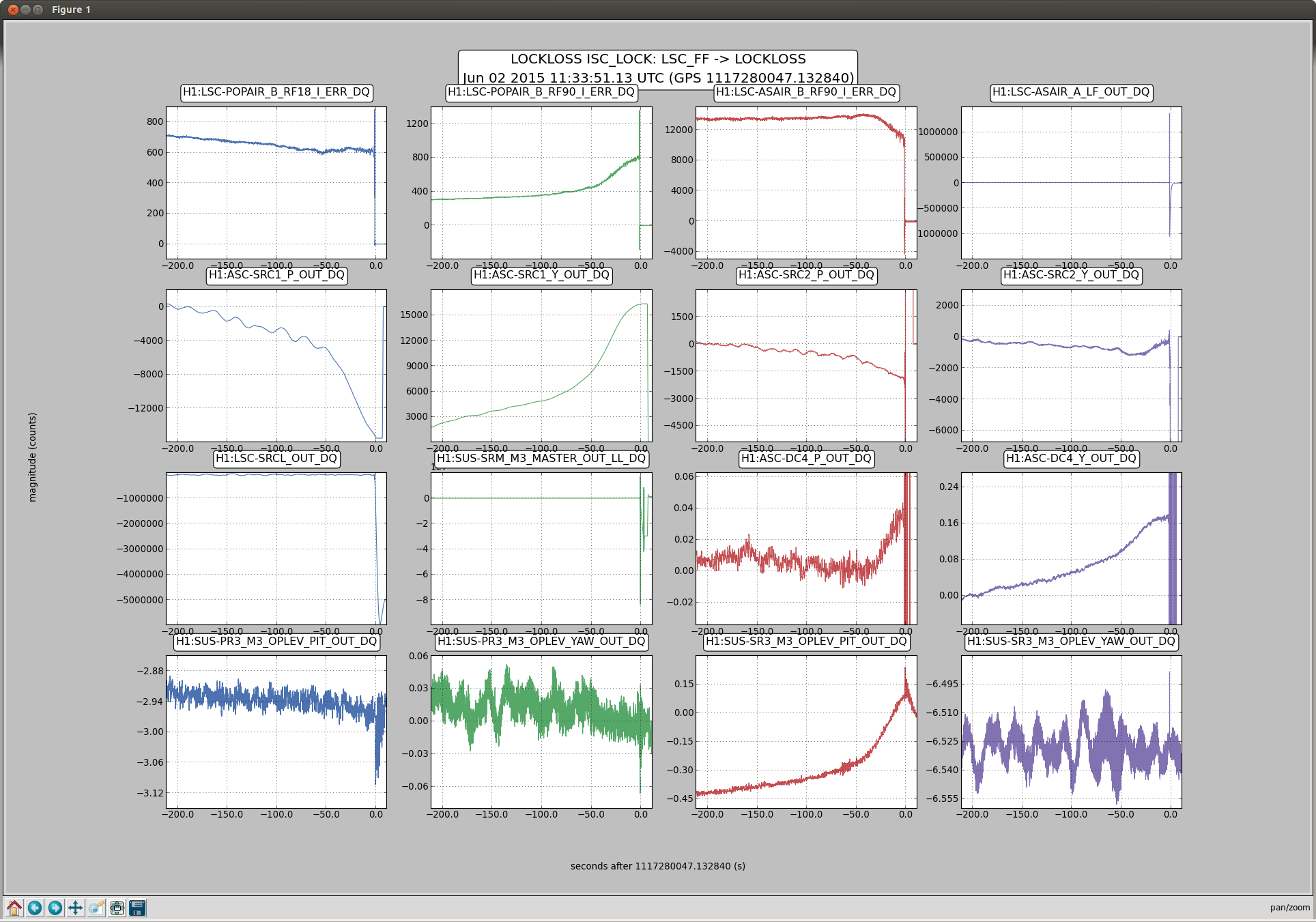
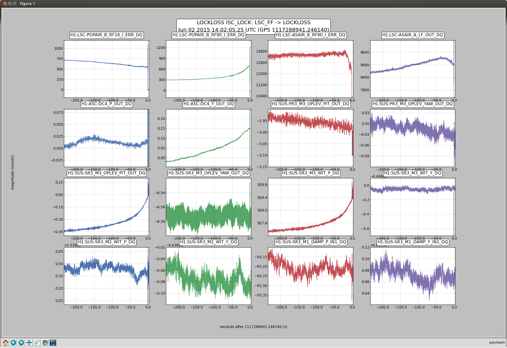
Daniel and I looked at three of the locklosses from Travis's shift last night, from 14:40, 14:02 and 11:33 UTC. The earlier two both seem to be related to an alignment drift over 2-3 minutes before the lockloss, which shows up clearly in SR3 PIT. (there is currently not feedback to SR3 PIT) According to the witness sensors, this drift is only seen on M3. No optics saturated until after the lockloss. The DC4 centering loop, as well as both of the SRC alignment loops respond to the drift.
Its unclear what causes the drift to accelerate in the minutes before the lockloss. There is also a drfit of SR3 when we power up, as we noted yesterday, but this happens on a slower timescale than the dirfts that preceed a lockloss (3rd screenshot). Also, there is a longer, slow drift that happens whenever we are locked.
With Patrick and Cheryl I have engaged a DC coupled optical lever for SR3 PIT, we will see if this helps. The last screen shot attached shows the MEDM screen used to turn this on or off.
If the operators need to disable this (due to an earthquake, a trip, or if the optic becomes misalinged for any other reason) you can get to this screen from SR3, M2 OLDAMP.
Turning off:
turn off FM1 (labeled DC), then the input
Turning it back on:
Once the optic has settled and the beam is back on the oplev QPD, turn on the damping loop (with FM1 still off). Average INMON (in a command line tdsavg 10 H1:SUS-SR3_M2_OLDAMP_P_INMON), type -1 times the average into the offset, make sure the offset is engaged, and finally turn on FM1 to make the loop DC coupled.
Since this is just a trial, Jeff is not including these changes in his current SDF cleanup campaign.
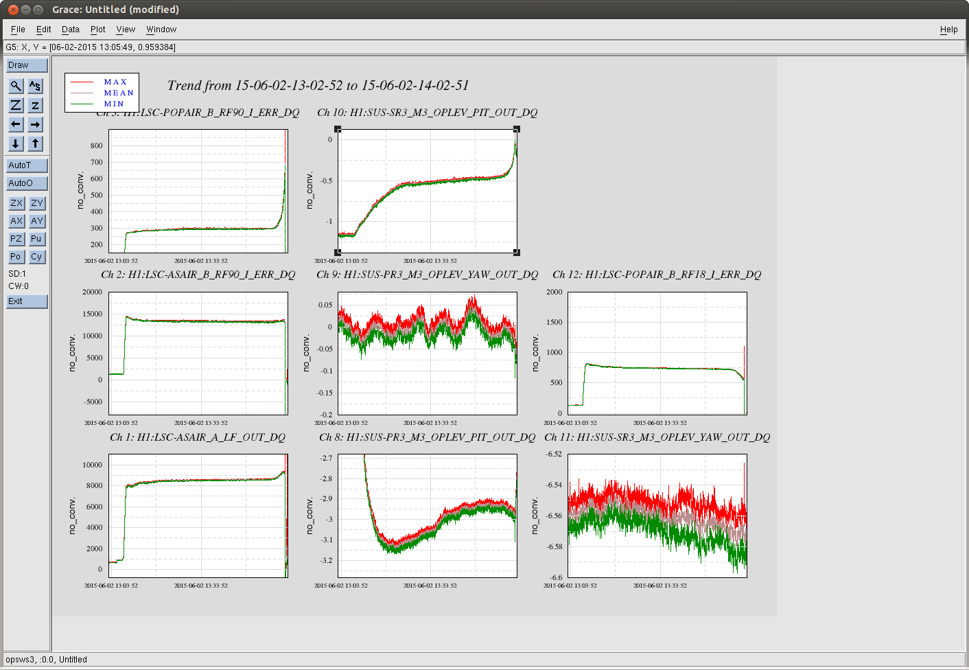

Looking at the initial power up, we can see that an increase of a factor of ~10 causes ~0.7 µrad of pitch misalignment. During the accelerated drift in the last 3-5 minutes before the lock loss another 0.4 µrad of pitch misalignment was acquired with only ~10% of power increase. One might wonder, if we see a geometrically induced wire heating run away.
I modeled how much the two front wires have to heat up to casue a bottom mass pitch of 1 microradian. A very small temperature increase is needed to predict this.
* Assuming a constant temperature profile along the wire length (I'm sure this is not the case, but it is easy to calculate), it is
0.003 [C]
* Assuming a linear temperature profile where with the max temperature is in the middle, and the ends of the wire have no temperature increase
0.006 [C]
So we can say an order of magnitude estimate is greater than 1 mC / urad and less than 10 mC / urad.
Calculations:
From gwinc, the thermal coefficient of expansion for C70 steel wire is
alpha = 12e-6 [1/C].
From the HLTS model at ../SusSVN/sus/trunk/Common/MatlabTools/TripleModel_Production/hltsopt_wire.m
wire length L = 0.255 [m]
front-back wire spacing s = 0.01 [m]
The change in wire length for pitch = 1 urad is then
dL = s * pitch = 0.01 * 1e-6 = 1e-8 [m]
* For uniform wire heating of dT, this change comes from
dL = alpha * L * dT
So, solving for dT
dT = dL / (alpha * L) = 1e-8 / ( 12e-6 * 0.255 ) = 0.0033 [C]
* For a linear temperature increase profile (max at middle, 0 at ends), I break the wire into many constant temperature segments of length Lsegment.
The temperature increase profile is a vector defined by
dT = dTmax * TempPrile
where TempProfile is a vector of the normalized shape of the temperature prodile. It is triangular, 0 at the ends and 1 at the peak in the middle. Each element of the vector corresponds to a constant temperature segment of the wire. dTmax is a scalar representing the maximum temeprature increase at the middle of the wire.
The change in wire length is then given by
dL = sum( alpha * Lsegment * TempProfile ) * dTmax
solving for dTmax
dTmax = dL / sum( alpha * Lsegment * TempProfile )
with 101 segments, this gives us
dTmax = 0.0063 [C]
about double the uniform heating case.
* I also considered that since the wire has significant stress due to the test mass weight, the Young's modulus's temperature dependence might cause a different effective thermal expansion coefficient alpha_effective. This appears to be a negligible effect.
From gwinc, the temperate dependence of the young's modulus E is
dE/dT = -2.5e-4 [1/C]
and young's modulus E is
E = 212e9 [Pa]
from https://alog.ligo-la.caltech.edu/aLOG/index.php?callRep=12581, we know that the change in spring length due to the modulus of eleasticity dependence is
dL = -dE/dT * dT * Tension / Stiffness
where Tension is the load in the wire and Stiffness is the vertical stiffness of the wire.
The Stiffness is given by
Stiffness = E * A / L = E * pi * r^2 / L
where A is the cross sectional area of the wire, and r is the radius.
So plugging this in above
dL = -dE/dT * dT * Tension * L / ( E * pi * r^2 )
We get the correction on alpha by dividing this by L and dT, which eliminates both from the equation. From the HLTS model, the bottom mass is 12.142 kg and the wire radius is 1.346e-4 m.
Tension = 12.142 * 9.81 / 4 = 29.8 [N]
The correction on alpha is then
-dE/dT * Tension / ( E * pi * r^2 ) = 2.5e-4 * 29.8 / (212e9 * pi * 1.346e-4^2) = 6.2e-7 [1/C]
This changes alpha from
12e-6 to 12.6e-6 [1/C]
Not enough to matter for the estimates above.
Localizing the heat source:
I made a calculation of the heat absorption by wires.
Based on Brett's temperature estimate, assuming the radiation as the only heat dissipation mechanism, the heat the front wires should be absorbing is about 1uW total per two wires when SR3 tilts by 1 urad regardless of the temperature distribution.
If you only look at the power, any ghost beam coming from PRC power (about 800W per 20W input assuming recycling gain of 40) can supply 1uW as each of these beams has O(10mW) or more.
I looked at BS AR reflection of X reflection, CP wedge AR both ways, and ITM AR both ways. I'm not sure about the first one, but the rest are mostly untouched by anything and falls on SR3 off centered.
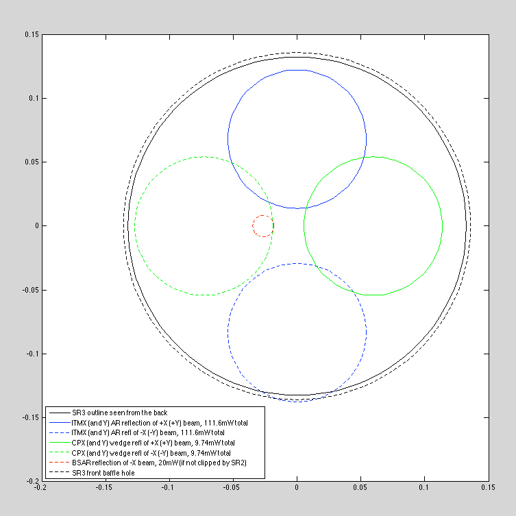
The attachment depicts SR3 outline together with the position of CP wedge AR (green) and ITM AR (blue) reflections, assuming the perfect centering of the main beam and the SR3 baffle on SR3. Note that ITMX AR reflection of +X propagating beam falls roughly on the same position on SR3 as ITMY AR reflection of +Y propagating beam. Ditto for all ITM and CP AR reflections. The radius of these circles represent the beam radius. The power is simply 20W*G_rec(40)*(AR(X)+AR(Y))/4 (extra factor of 2 due to the fact that the AR beam goes through the BS) for ITM and CP, and 20W*40*AR/2 for BSAR of -X beam.
I haven't done any more calculations and I don't intend to, but just by looking at the numbers (total power in green and blue beams in the figure is about 240mW, 5 orders of magnitude larger than the heat absorbed by wires), and considering that the centering on SR3 cannot be perfect, and that SR3 baffle is somewhat larger than SR3 itself, and that CP alignment is somewhat arbitrary, it could be that these blobs seeps through the space between the baffle and the SR3 and provide 1uW.
The red thing is where BSAR reflection of -X beam would be if it is not clipped by the SR2 scraper baffle. If everything is as designed, SR2 scraper baffle will cut off 90% of the power (SR2 edge is 5mm outside of the center of the beam with 8mm radius), and remaining 10% comes back to the left edge of the red circle.
Any ghost beam originating from SRC power is (almost) exhonerated, because the wire (0.0106"=0.27mm diameter) is much smaller than any of the known beams such that it's difficult for these beams to dump 1uW on wires. For example the SRC power hitting SRM is about 600mW per 20W input, SRM AR reflection is already about 22uW.
Details of heat absorption:
When the temperature on a section of wire rises, the stretching of that section is proportional to the length of that section itself and the rise in temperature. Due to this, the total wire stretch is proportional to the temperature rise integrated over the wire length (which is equial to the mean temperature rise multiplied by the wire length) regardless of the temperature distribution as is shown in effect by Brett's calculation:
stretch prop int^L_0 t dL = mean(t) * L
where L is the length of the wire and t is the difference from the room temperature.
Likewise, the heat dissipation of a short wire section of the length dL at temperature T+t via radiation is
sigma*E*C*dL*[(T+t)^4-T^4] ~ 4*sigma*E*C*dL*T^3*t
where sigma is Stefan-Boltzmann constant, E the emmissivity, C the circumference of the wire, T the room temperature (about 300K). The heat dissipation for the entire length of wire is obtained by integrating this over the length, and the relevant integral is int^L_0 t dL, so again the heat dissipation via radiation is proportional to the temperature rise integrated over the wire length regardless of the temperature distribution:
P(radiation) ~ 4*sigma*E*T^3*(C*L)*mean(t).
I assume the emmissivity E of the steel wire surface to be O(0.1). These wires are drawn, couldn't find the emissivity but it's 0.07 for polished steel surface and 0.24 for rolled steel plate.
I used T=300K, t=3mK (Brett's calculation for both of the temperature distributions), C=pi*0.0106", L=0.255m*2 for two front wires, and obtained:
P(radiation) ~ 0.8uW ~ 1uW.
ITM AR:
ITM has a wedge of 0.08 deg, thick side down.
ITM AR reflection of the beam propagating toward ETM is deflected by 2*wedge in +Z direction. For the beam propagating toward BS, ITM AR reflects the beam, deflecting down, and this beam is reflected by ITM and comes back to BS. Deflection of this beam relative to the main bean is -(1+n)*wedge.
AR beam displacement at BS is +14mm for +Z-deflection and -17mm for -Z-deflection. Since the BS baffle hole "radius" seen from ITMs is 100+ mm, and since the beam radius is about 53mm, AR beams are not blocked much by BS baffle and reaches SR3.
ITM AR reflectivity is about 300ppm.
CP AR:
Similar calculation for CP except that they have horizontal wedge, thick part being -Y for CPX and -X for CPY.
CP wedge is about 0.07 degrees.
I only looked at the surface of CP that is opposite of the ITM, and assumed that the surface facing ITM is more or less parallel to ITM AR, within an accuracy of O(100urad).
I assumed that S1 is the surface close to the ITM, and took S2 AR numbers from galaxy web page (43.7ppm for X, 5ppm for Y).
BS AR propagation:
BS wedge is 0.076 degrees, with a reflectivity of 50ppm.
Deflection of BS AR reflection of -X beam relative to the main beam is NOT -2*wedge as BS is tilted by 45 degrees. With some calculation it turns out that it is about -0.27 degrees, with a displacement of +48mm (positive = +X).
This beam is not obstructed at all by the BS baffle, hits SR3 and makes it to SR2 baffle edge. What made it to the SR2 surface doesn't go to SRM and instead comes back to SR3 as SR2 is convex and the beam is heavily off-centered.
If there's no SR2 baffle and if SR2 is much larger, the center of the reflected beam is going to be 50cm in -X direction from the center of SRM, which happens to be on SR3.
I don't know what happens to the edge scattering and the reflection from SR2, but both of these are highly dependent on SR2 centering.