jeffrey.bartlett@LIGO.ORG - posted 17:13, Wednesday 15 September 2010 (188)
BS Top Stage Cartridge Assembly
We have completed the assembly of the five Beam Splitter Top Stage cartridges, which are undergoing the 100-hour creak bake.
Assembly Notes:
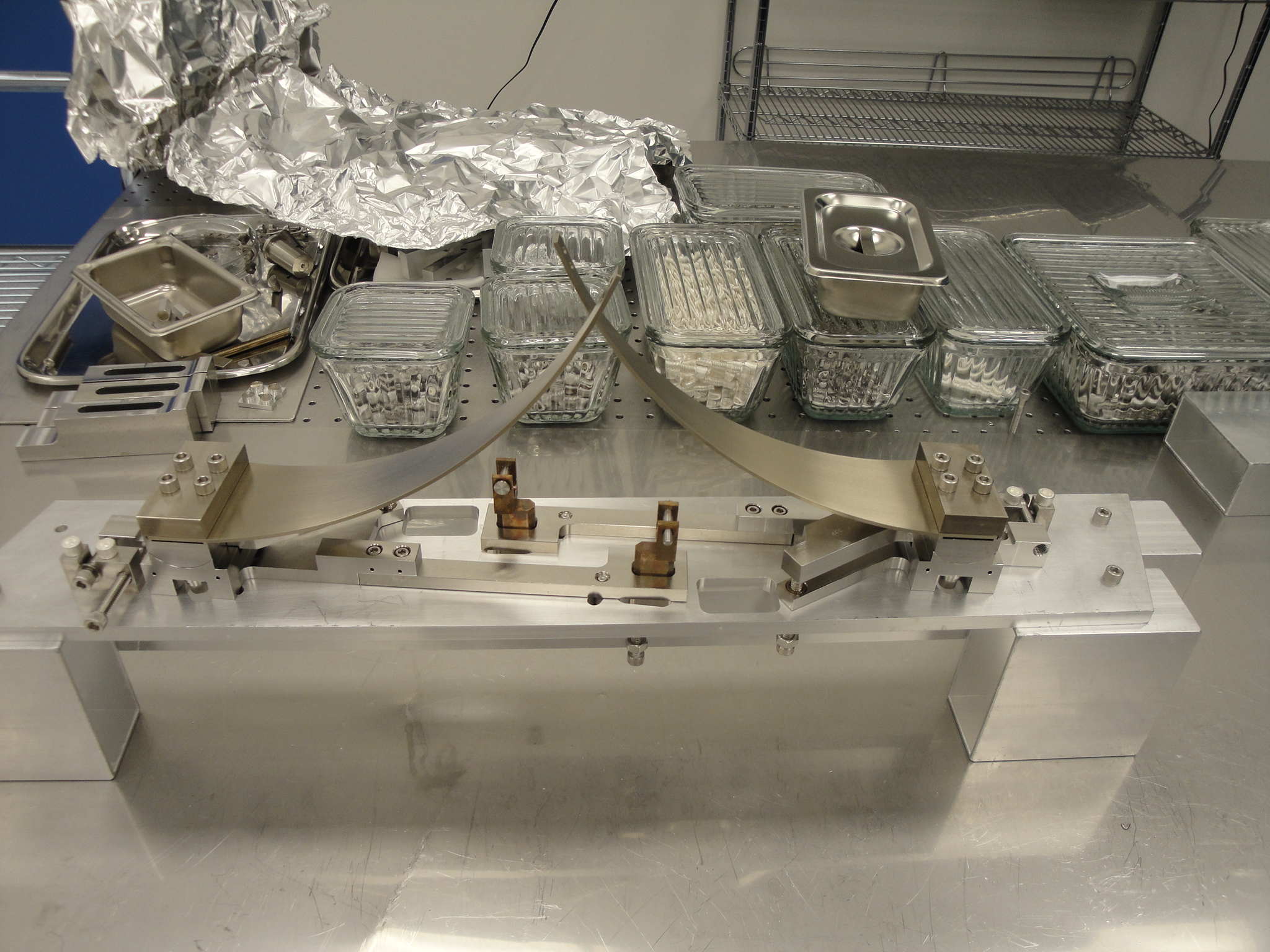
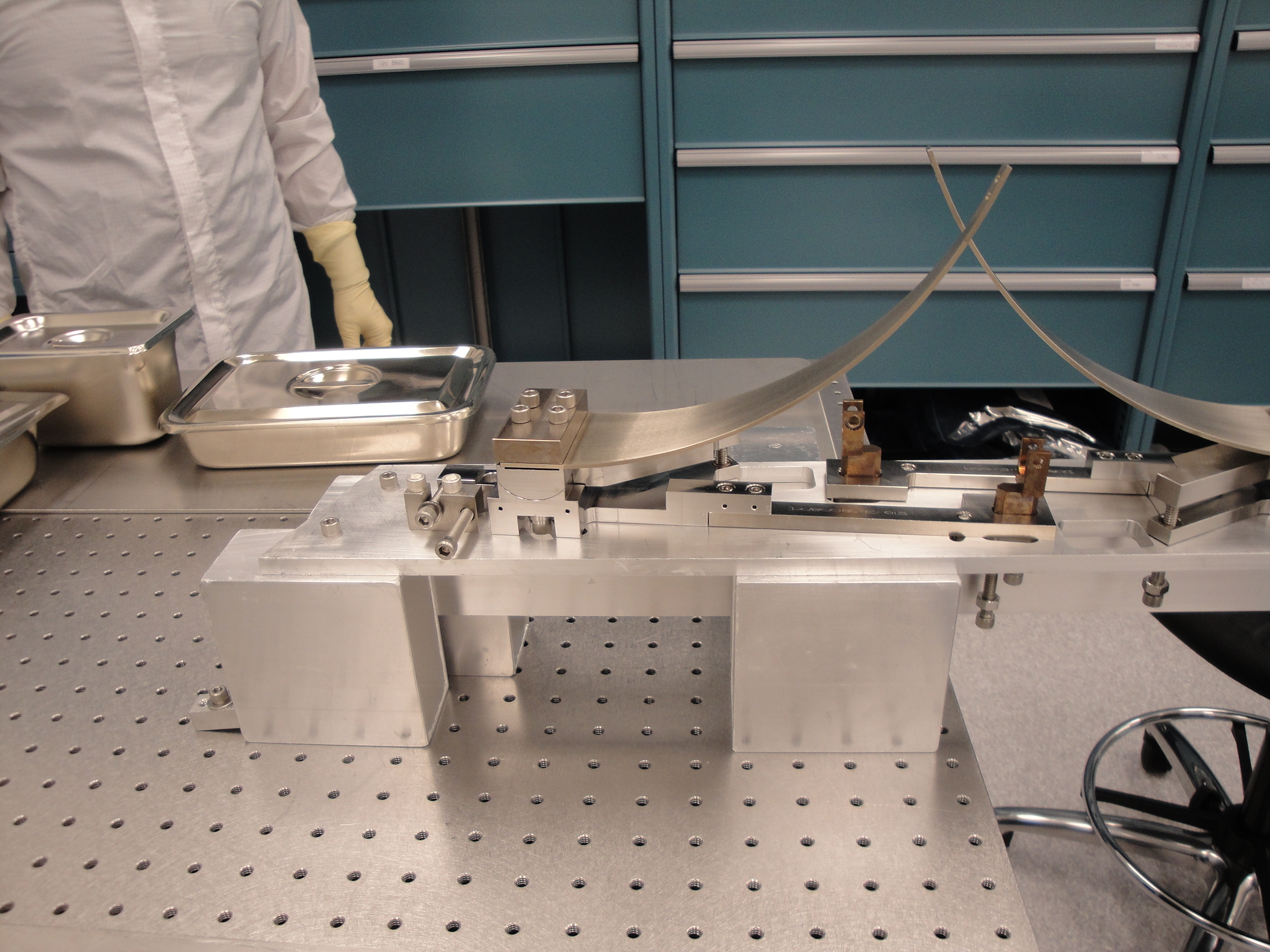
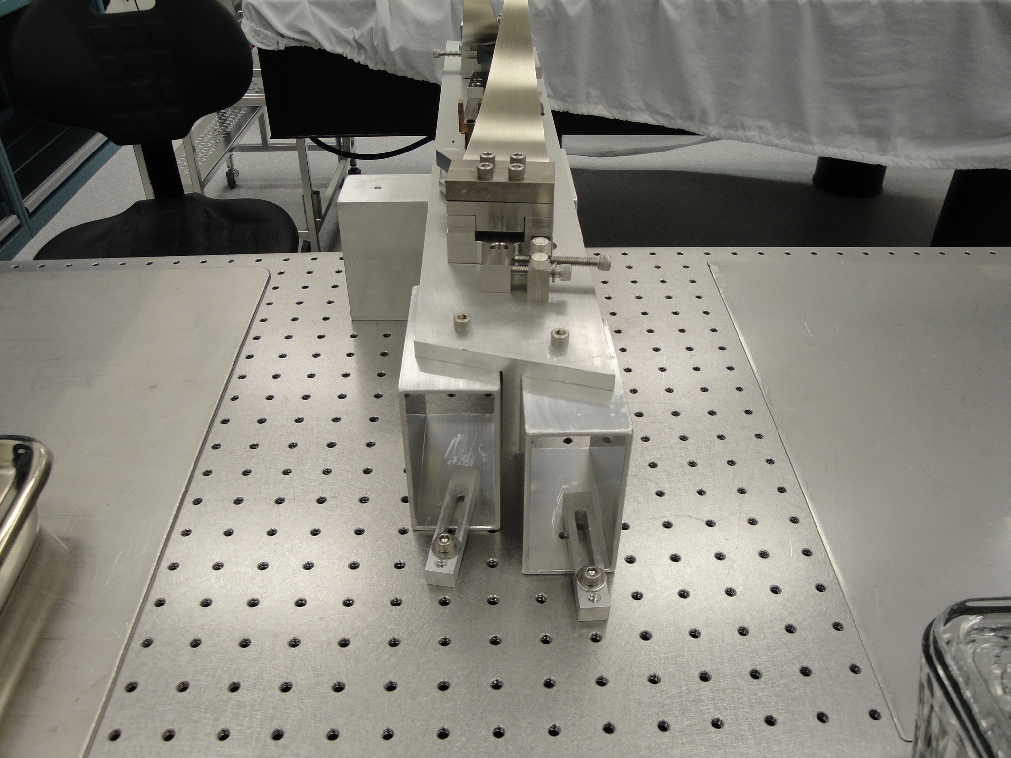
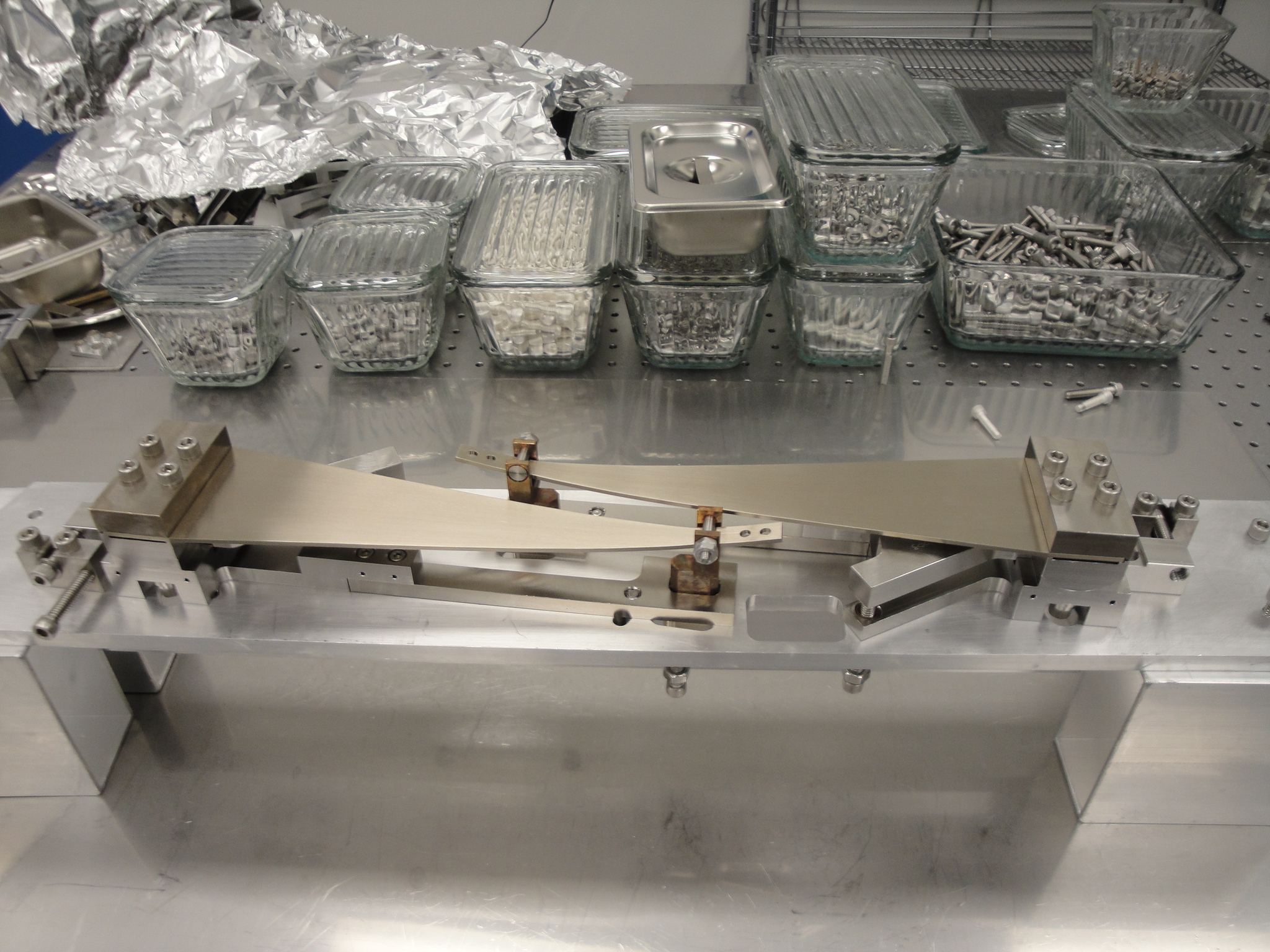
(1). We made the assembly jig out of four sections of aluminum box. For assembly, the end of the Base Plate is secured to the box sections via 1/4-20 SHCS into tapped holes. For blade pull down, the two end sections, bolted to the Base Plate, are dog clamped to the optics table. The remaining two box sections are slid under the Base Plate near the edge of the optics table to support the front half of the assembly. (See photos Assembly Jig and Clamp Down).
(2). When installing Helicoils into the Blade Clamp Bottom ensure the two outer ones are run down to the bottom (the curved side) of the clamp. If not the 1/4-20x 1” mounting bolts will not engage the Helicoil.
(3). The Rotational Bushing can be a tight or loose fit in the Bottom Plate or Blade Clamp Base. If you have to tap or press to set the bushing, install a 1/4-20 SHCS into the bushing and push on the head of the SHCS. Tapping or pressing directly on the phosphors bronze will distort the bushing making it difficult to insert into the other part.
(4). If the mounting SHCS for the adjuster assembly do not line up with the slots cut into the Base Plate, loosen the 8-32 SHCS holding the two halves together to allow some free play. Once all five SHCS have been installed, the 8-32s can be tightened back down. This may cause some binding when trying to rotate the adjuster.
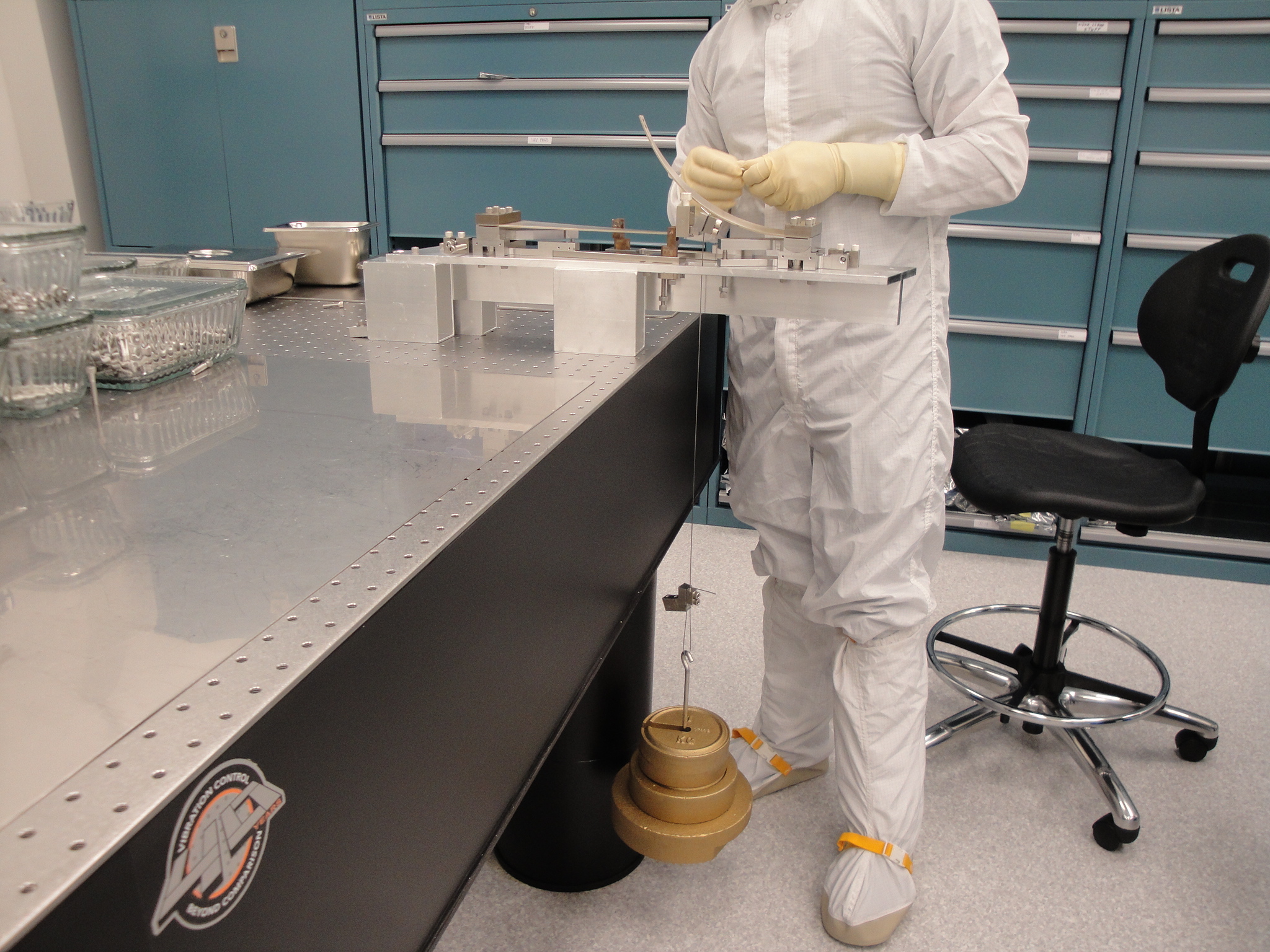
(5). Use 20kg for the blade pull down weight. The assembly book calls for 50kg, which is too much.
Images attached to this report