For some guidance regarding beam centering in HAM6, I post here the estimated Gouy phase for the optical elements between SR3 and the OMC. The a la mode script that was used is attached, along with the parameters file which uses the best available positions of H1 optical elements in HAM6. This is the same material that was posted in alog:14023, here I add information and SR2, SR3, and AS_C.
| Optic / sensor | Gouy phase (deg) |
| SR3 | 47 |
| SR2 | 48 |
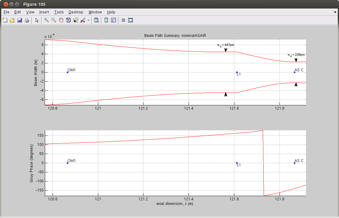
| AS_C | -171 |
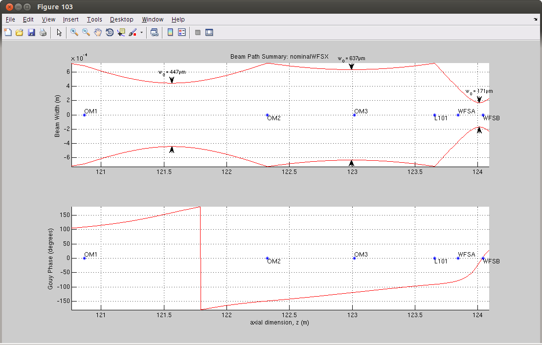
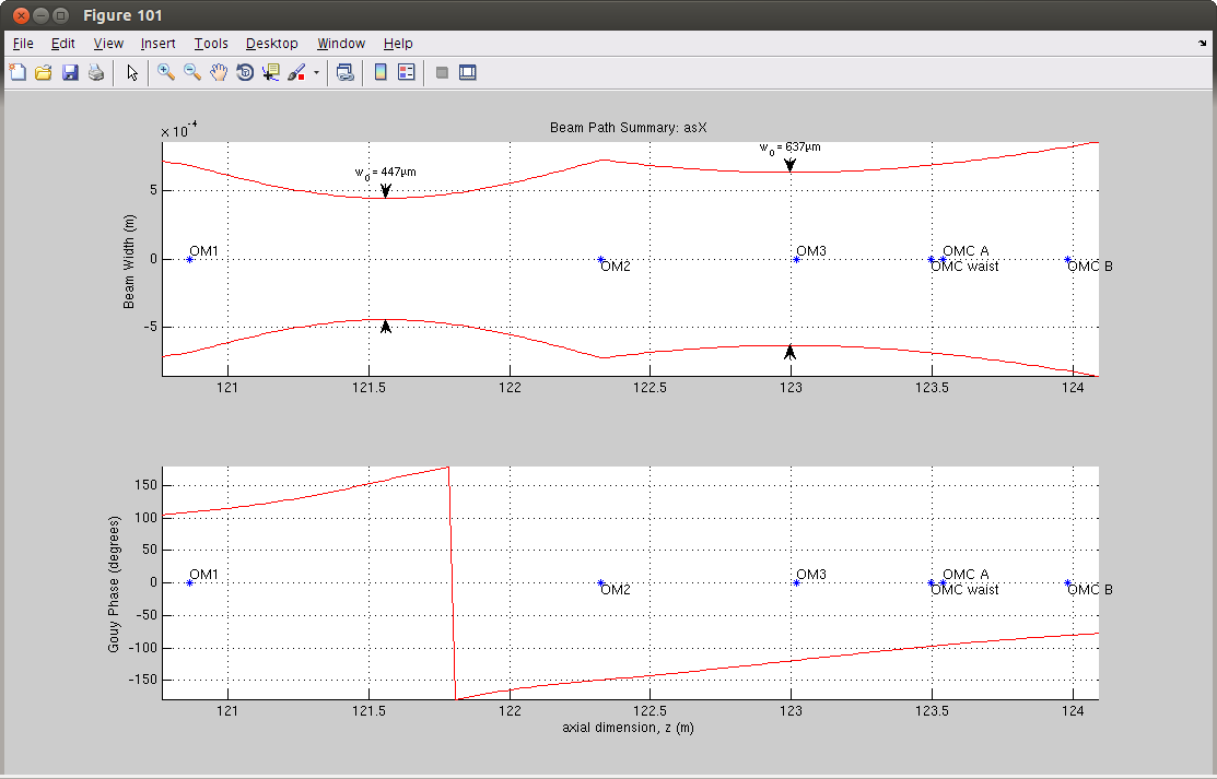
| OM1 | 109 |
| OM2 | -149 |
| AS_A | -78 |
| AS_B | 4 |
| OM3 | -119 |
| OMC QPD A | -95 |
| OMC QPD B | -80 |
From these results there's no obvious pairings of actuator --> sensor, except for OM1 --> AS_B and OM2 --> AS_A, which is essentially what we're using right now. The OMC QPDs are degenerate, but we construct a waist basis for the OMC alignment, {OMC_A, OMC_B} --> {POS, ANG} using the known geometry of the OMC breadboard.
The plots attached show the beam propagation for the path from OM1 to AS_C, the AS WFS, and the OMC, respectively. Note that these beam propagations are for a single-bounce beam from ITMX. We know the mode from the full IFO is different (because the mode-matching into the OMC is different, between a single bounce and the full IFO), but it's not a large difference.
Anyways we shouldn't rely on simulation, we should measure the sensing matrix from {SR3,SR2, OM1, OM2, OM3} --> {AS_A, AS_B, AS_C, OMCA, OMCB} and work out a control scheme.
The a la mode script and parameters file are attached.