Calibration Team
Sign of h(t):
The gravitational wave strain h(t) is given by h(t) = Delta L/L where Delta L is is computed using
Delta L = ± (Lx - Ly)
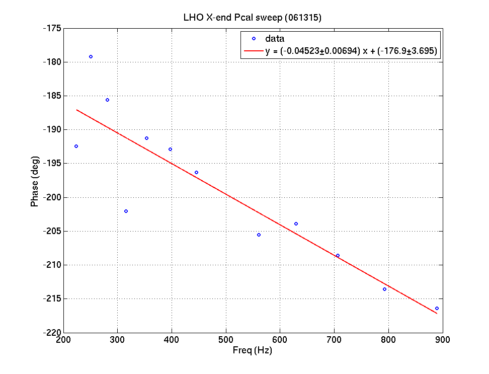
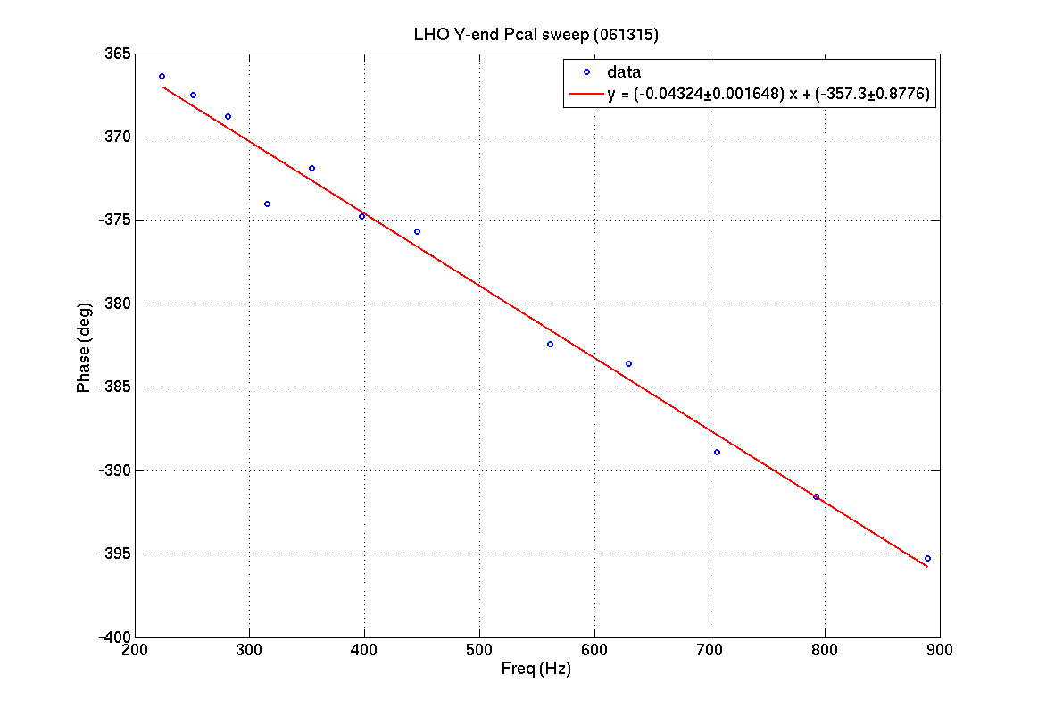
The sign of Delta L can be determined using Pcal actuation on the test mass. Pcal only introduces a push force so pcal readout signal (truly pcal excitation) is minimum when the testmass is away from the corner station (closer to pcal laser). From the first plot the phase between DARM/PCAL is ~ -180 degrees (DARM lags PCAL) which suggests that DARM signal from ETMX will be maximum when pcal is minimum (ETMX further away from corner station). Similarly, from second plot, since DARM and PCAL have a phase difference of ~-360 degrees (essentially 0 degrees), the DARM signal from ETMY is minimum when the pcal is minimum. This shows that the sign convention for the Delta L is '+'
Time Delay between Pcal and DARM:
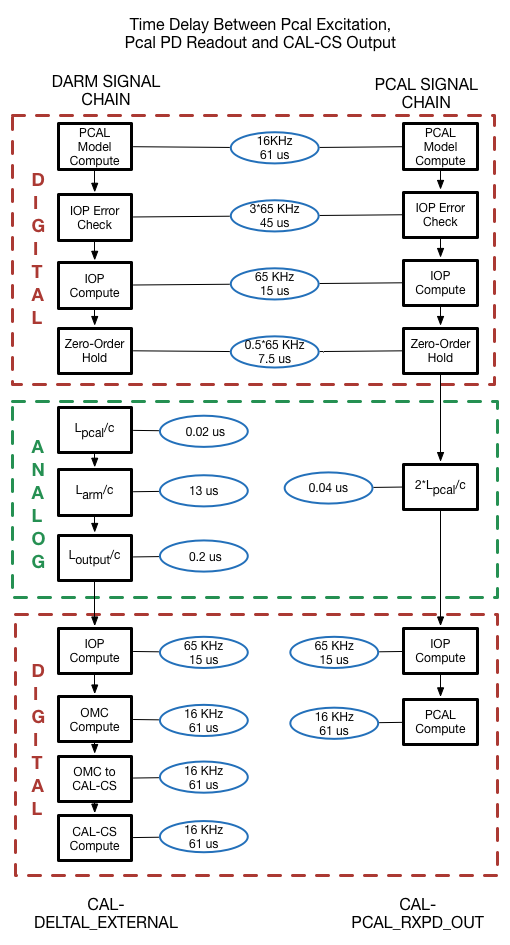
Also the slope of the curve gives the time delay between Pcal and DARM signal chain. The time delay is about 125±20 us. This time delay can be accounted for, within the uncertainity, from the difference in signal readout chain outlined in Figure 3 attached.
Refer to LLO alog #18406 for the detailed explanation behind this conclusion.
I believe this sign check and the sign check at LLO are correct.  For the record, below is how I reached that conclusion:

The photon calibrator laser can only push, but there is a nonzero baseline intensity and you modulate the intensity around that.  The question is, if you apply a positive voltage to the PCAL system input, do you get more force or less force on the test mass?  Figure 21 of the PCAL final design document seems to show that the undiffracted beam through the AOM is what is sent to the test mass, so increasing the amplitude of the 80 MHz drive to the AOM REDUCES the force on the test mass.  However, the AOM driver electronics could introduce a sign flip when it conditions the input voltage.  To check that, I pulled up PCAL excitation and receiver photodiode data (e.g. H1:CAL-PCALX_EXC_SUM_DQ and H1:CAL-PCALX_RX_PD_OUT_DQ) and plotted a short time interval at GPS 1117933216.  I saw that the PCAL photodiode signal variations are basically in phase with the PCAL input excitation, with just a ~30-40 degree phase lag at ~500 Hz, presumably from filter delay.  So, applying a positive voltage to the PCAL system input causes more force on the test mass, and anyway the PCAL receiver photodiode measures intensity directly.  I confirmed this for all four PCALs (H1 and L1, X and Y) and also confirmed that the transmitter and receiver photodiodes vary together.

The PCAL pushes on the front of the ETM, i.e. on the face that the primary interferometer beam reflects off of.  This being a pendulum, the ETM is closest to the laser (i.e., the arm is shortest) when the force is at its MAXIMUM.  LLO alog 18406 has a comment consistent with that: "Theory of pendulums suggests that Pcal signal will be minimum when ETM swings further away from corner station".  LHO alog 19186, above, has a statement, "pcal readout signal (truly pcal excitation) is minimum when the testmass is away from the corner station (closer to pcal laser)", which is more ambiguous because the ETM being away from the corner station would put it FARTHER from the PCAL laser.  But both draw the correct conclusion from the data: with the intended sign convention, DARM should be at its positive maximum when the X arm is longest (ETMX is farthest from the corner station; PCALX intensity is at its minimum) or when the Y arm is shortest (ETMY is closest to the corner station; PCALY intensity is at its maximum), and that is what was reported at both sites.
Peter,
I disagree with one assumption in your argument, but it does not disprove (or support) the rest of your conclusions.
"The question is, if you apply a positive voltage to the PCAL system input, do you get more force or less force on the test mass? Figure 21 of the PCAL final design document seems to show that the undiffracted beam through the AOM is what is sent to the test mass, so increasing the amplitude of the 80 MHz drive to the AOM REDUCES the force on the test mass. However, the AOM driver electronics could introduce a sign flip when it conditions the input voltage."
As far as I know there's no sign flip in AOM electronics. Undiffracted beam gets dumped in BD2, while diffracted beam is sent to the ETM.
Unfortunately I couldn't find an explicit noting of it in our recent DCC documents.
Oh, the diffracted beam gets sent to the test mass?  Then I agree, there isn't a sign flip in the electronics.  (In figure 21 in the document, it looks like the undiffracted beam went to the test mass.)

BTW, I've posted a multi-frequency look at the hardware injection actuation sign (and amplitudes and time delays) at https://wiki.ligo.org/Main/HWInjER7CheckSGs.