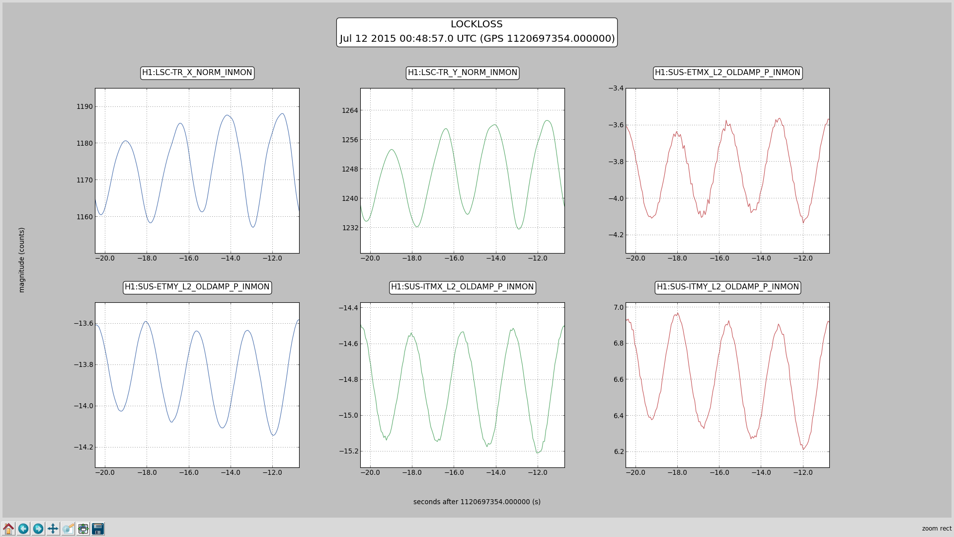
Sheila, Evan, Stefan,
With information for Sheila on Sun morning

We tried to operate the ASC system at full power (24W), using two different sets of QPD offsets (I'll call them pre-vent and post-vent, see burt files below).

With the pre-vent offsets we
 - The ASC system was stable at full input power
 - We had a recycling gain of about 36. (Based on transmitted power.)
 - These QPD offsets are not compatible with the current initial alignment (i.e. the Guardian will drop lock during ENGAGE_ASC - however a slow 2-min offset ramp from post-vent to pre-vent, with 20dB lower gains on the ITM loops worked)

With the post-vent offsets we
 - Get a recycling gain of 40. (Based on transmitted power.)
 - These QPD offsets are compatible with the current initial alignment. The ENGAGE_ASC step works fine.
 - Assuming the higher recycling gain is real (and not due to a difference in QPD clipping), we'd like to keep those QPD offsets because of the higher recycling gain.
 - However we get a 0.41Hz oscillation which starts at about 20W or 21W.


About this 0.41Hz oscillation:
 - It shows up in arm build-up's as 0.41Hz modulation (i.e. 1-f).
 - It is CSOFT PITCH, i.e. all 4 test mass optical levers show it exactly in phase.
 - The arm powers are exactly out-of-phase with the optical level pitch signals, i.e. when all optics point downward (highest OL value), the arm power is at a minimum. (see plot)
 -

To deal with this mode, we switched the ITM ASC loops for PITCH to the common/differential basis (i.e. DSOFT is now DITM, and CSOFT is now CITM). At the time of this elog we were still designing a filter to stabilize the oscillation.


========================================================================================
Pre-vent QPD offsets (in /ligo/home/evan.hall/Public/Burt/ItmQPDsPre.snap burt file):
H1:ASC-X_TR_A_PIT_OFFSET 1 -2.900000000000000e-02
H1:ASC-X_TR_B_PIT_OFFSET 1 -1.580000000000000e-01
H1:ASC-X_TR_A_YAW_OFFSET 1 -7.000000000000000e-03
H1:ASC-X_TR_B_YAW_OFFSET 1 1.050000000000000e-01
H1:ASC-Y_TR_A_PIT_OFFSET 1 1.010000000000000e-01
H1:ASC-Y_TR_B_PIT_OFFSET 1 -5.600000000000000e-02
H1:ASC-Y_TR_A_YAW_OFFSET 1 -1.270000000000000e-01
H1:ASC-Y_TR_B_YAW_OFFSET 1 5.500000000000000e-02

Post-vent QPD offsets (in /ligo/home/evan.hall/Public/Burt/ItmQPDsPost.snap burt file):
H1:ASC-X_TR_A_PIT_OFFSET 1 -4.800000000000000e-02
H1:ASC-X_TR_B_PIT_OFFSET 1 -1.480000000000000e-01
H1:ASC-X_TR_A_YAW_OFFSET 1 -4.000000000000000e-03
H1:ASC-X_TR_B_YAW_OFFSET 1 7.800000000000000e-02
H1:ASC-Y_TR_A_PIT_OFFSET 1 -1.180000000000000e-01
H1:ASC-Y_TR_B_PIT_OFFSET 1 -3.690000000000000e-01
H1:ASC-Y_TR_A_YAW_OFFSET 1 -2.420000000000000e-01
H1:ASC-Y_TR_B_YAW_OFFSET 1 -3.180000000000000e-01
After switching the ITM basis to common/differential, we tried for a while to measure the cITM pitch loop to see if we could put it to work in mitigating this 0.4 Hz resonance.
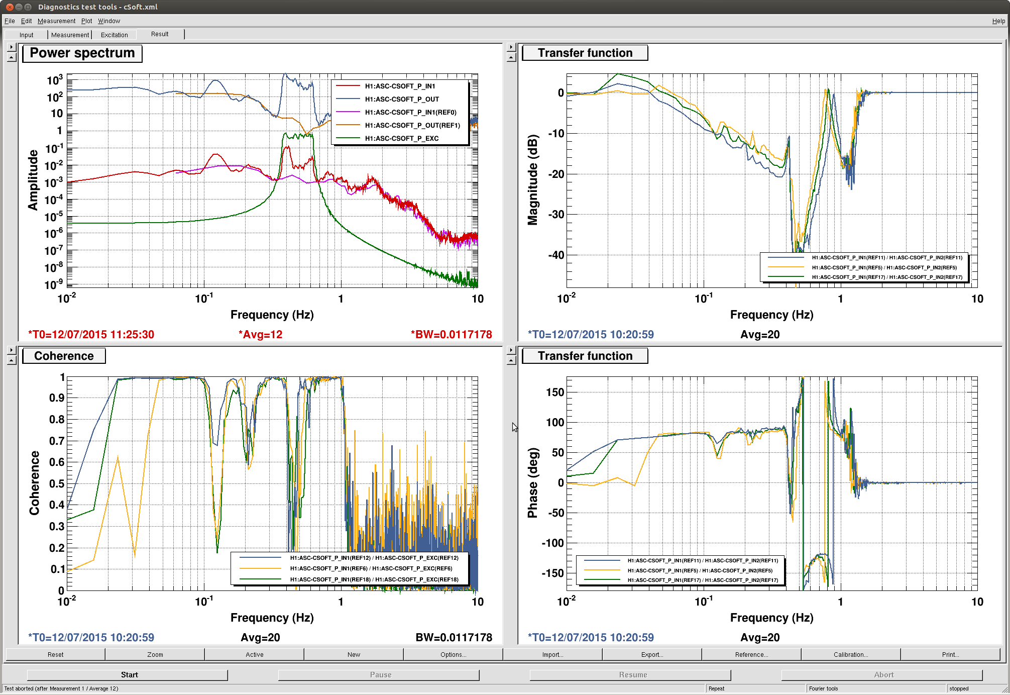
The attachment shows the loop OLTF at several different powers (yellow: 8W; green: 11 W; blue: 18 W). First, the ugf of the main, 1/f portion of the loop is about 40 mHz. Second, around 0.8 Hz there is a power-dependent resonance which is probably the hard mode. Third, we can see the 0.4 Hz resonance in the cITM loop, although the coherence of the measurement is not great between 0.4 Hz and 0.6 Hz. This makes the behavior of the TF around this resonance hard to interpret. Under the assumption that it's just a pair of complex poles, this means that the total TF will have a 180° lag at the resonance, and hence the loop will go unstable if the gain is increased too much. Hence this current loop shape cannot be used to control the instability.
Therefore, we designed a filter (FM6 in the cSoft filter bank) which flips the sign of the feedback near this resonance. It is a complex pair of RHP zeros at 0.3 Hz, and a complex pair of poles at 0.5 Hz. Together they give 180° of lag at 0.4 Hz. (There is also about 30° of lead and 10 dB of gain near the hard mode.)
We flipped this filter on and off a few times in lock at 18 W, and it seems to correlate well with the apperance and disappearance of the 0.41 Hz oscillation in the ITM error signals, the test mass oplevs, the arm buildups, and the sideband buildups. A quick OLTF shows that the suppression is pretty marginal; probably less than 2 dB. This is with the filter gain increased from -0.3 to -0.8.