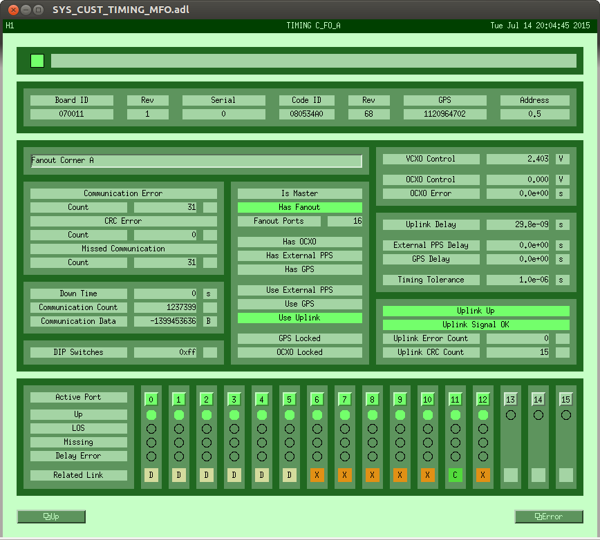
J. Kissel, S. Dwyer, D. Barker, J. Driggers, E. Hall

Some of the way through recovery (there will be a LONG aLOG to come; we're not yet fully covered), but we changed some hardware and the source of the problem hasn't been aLOGged yet, so I wanted to get this one in there separately.

Here's the story:
- We get to ALS COMM and DIFF steps up the lock acquisition sequence. Part of the automated sequence is to search for the right COMM and DIFF VCO frequency for IR resonance.
- This process failed, because the channels used to track the VCO frequency, H1:ALS-C_COMM_VCO_FREQUENCY and H1:ALS-C_DIFF_VCO_FREQUENCY, were dead, reading identically zero.
- These channels are copies of channels produced by the timing fanout / timing comparator system, H1:SYS-TIMING_C_FO_A_PORT_11_SLAVE_CFC_FREQUENCY_1 and H1:SYS-TIMING_C_FO_A_PORT_11_SLAVE_CFC_FREQUENCY_2, which are renamed by the ALS Beckhoff code to something more human readable.
- Note the "PORT_11" part of the fanout / comparator channel name. This represents the port number of the timing fanout from which the comparator gets its timing reference. The ALS Beckhoff code, which is common to both observatories, has the PORT 11 hard-coded into it's PLC to define the channel renaming.
- After calling Dave, we found out that the timing comparator's reference signal had been moved from port 11 (12 on the front panel of the chassis) to port 15 (16 on the front panel) when the new 9.1 MHz oscillator was installed this morning. The new 9.1 MHz oscillator's reference was put in PORT 11. Because the port user changed from a comparator to a RF source, the timing fanout / comparator's channels and infrastructure totally changed, not to mention the signal that now populates those channels.
- We looked at LLO's timing MEDM screens to see that unlike LHO, they've left the timing comparator plugged into PORT 11, and stacked additional RF sources beyond it, instead of what was intended this morning, which was to keep all the RF sources together, and push the comparator off to the end. Again, because this is hard-coded into the Beckhoff PLC, and changing the PLC and rebooting the Beckhoff system ALWAYS causes more problems than its worth, we elected to revert the timing cables.
- We've moved the comparator's fiber back to PORT 11 (port 12 on the front panel), and put the 9.1 MHz into PORT 12 (port 13 on the front panel).
- It took some clicking of theses port numbers on the MEDM screen for the comparator and the 9.1 MHz to show all green (indeed, the 9.1 MHz took a little bit longer, because the OXCO had to resync, but it had been syncing all day, so it only took ~10 seconds).
- Once the comparator signal was restored, the ALS channels made sense again, and we instantly moved past that step in the lock acquisition sequence.

Lesson learned?
- Everything depends on something else, and every change you make to the IFO matters, even if you don't think it does.
- Please aLOG everything you do. EVERYTHING. Granted, even if you had, we probably wouldn't have put two and two together until calling Dave, but still. If we've changed the 9.1 MHz frequency reference, the main RF source for locking the IFO, it should be in the aLOG.

Fil, Evan, Sheila, Patrick, Jenne, Jeff, Kiwamu (Dave on phone)
We now use the new OCXO for the interferometer controls.
Since we had a trouble reading out the frequency counter outputs, we made a quick hack on two fibers for the night.
The new OCXO was installed in the rack in the electronics room by Fil this morning. The synchronization PLL worked fine as advertised by Daniel (alog 18855). I disconnected the old IFR function generator from the main modulation path and connected the OCXO to the input of the entire chain as a new RF source. I attenuated the output of the OCXO such that it meets the standard rf level of 10 dBm at the input of the next rf device (i.e. an rf distribution amplifier). So far it seems to be behaving good -- we could fully lock the interferometer with the new OCXO. Just for a record, the mechanical switches on the front panel has been configured to 9100230 Hz. We left the old IFR mounted and powered up in the rack. Currently the OCXO box is not rigidly mounted. Fil is going to nicely mount it hopefully during the next maintenance period. The OCXO is connected to channel 12 of the corner A fan out through fiber.
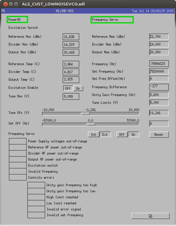
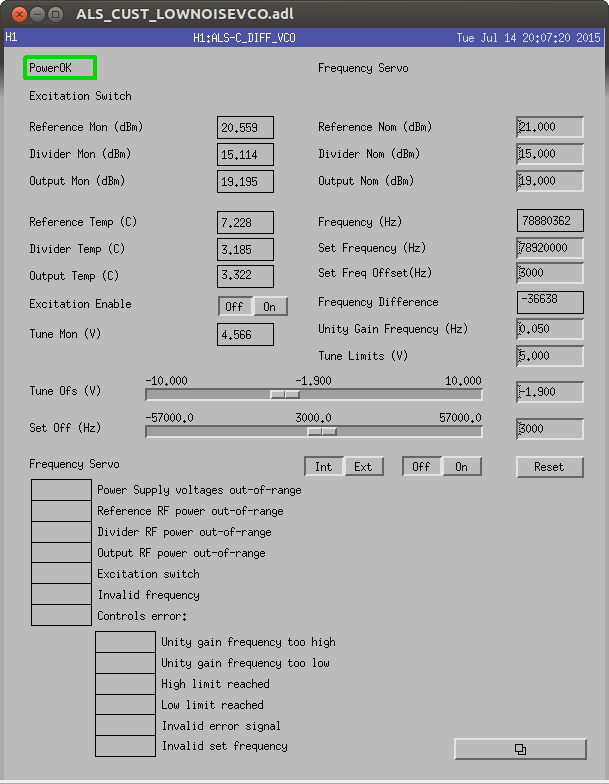
We had a trouble locking ALS comm because the frequency counter was reading zero Hz. This was also true for the rest of two VCOs -- IMC VCO and ALS DIFF VCO. But, since only ALS comm needs to read out the frequency through the counter during the locking sequence, we did not realize this issue until we started attempting full lock. Jeff spoke to Dave on phone and it turned out that there is a conflict between the actual fiber assignment and the Beckoff channel assignment in the corner A fan out because we physically changed the fiber assignment today. According to Dave, the swap was only between channels 11 and 15 (correct me if I am wrong). We decided to make a hack on the hardware side rather than updating the Beckoff code for tonight. We swapped fibers of channels 11 and 15 such that the ALS and IMC VCOs can read the data out of the usual fan out channel. This solution seem to have solved the issue for now. As of now, channel 11 is connected to the timing comparator and 15 is connected to an unused 80 MHz rf source.