Shivaraj, Darkhan
Summary
We replaced whitening filters on Delta L_{res} output channel with 2 zeros and 2 poles zpk, and Delta L_{ctrl} with 3 zeros and 3 poles zpk.
Details
Madeline uses FIR filters to dewhiten Delta L_{res} and Delta L_{ctrl} in GDS scripts. To make it easier to generate shorter dewhitening FIR filters for these channels she requested to replace the existing 5 zeros and 5 poles zpk filters in both of these channels with simpler, less poles and zeros zpk's.
Shivaraj designed new FIR filters for both of these channels, and we implemented them today around 1pm.
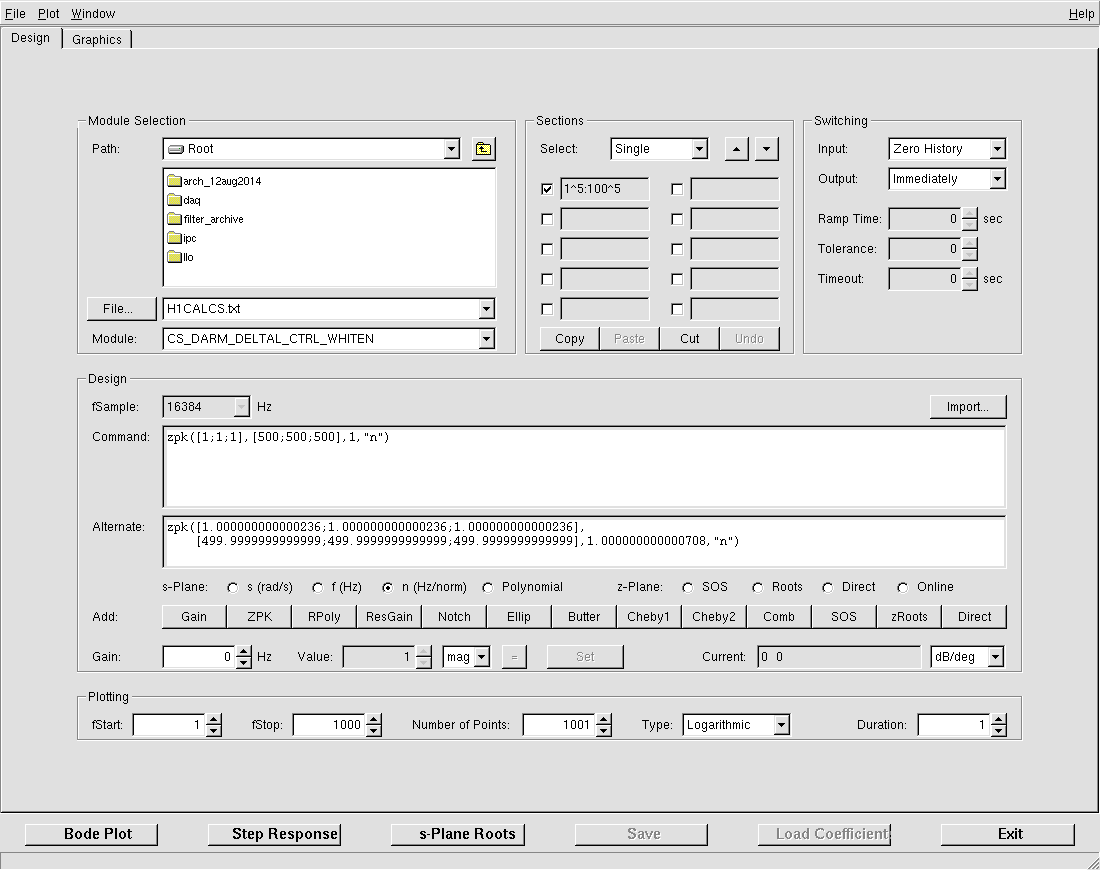
Power spectrum of H1:CAL-CS_DARM_DELTAL_CTRL_WHITEN_OUT before applying new whitening filter plotted in attached "H1-CAL-CS_DARM_DELTAL_CTRL_WHITEN_OUT_z5x1_p5x100_MAG.pdf". After applying new whitening filter, zpk([1; 1; 1], [500; 500; 500], 1), unfortunately the interferometer wasn't stable to take a spectrum measurement after I changed the filter, so I couldn't evaluate "whiteness" of the output in this channel.
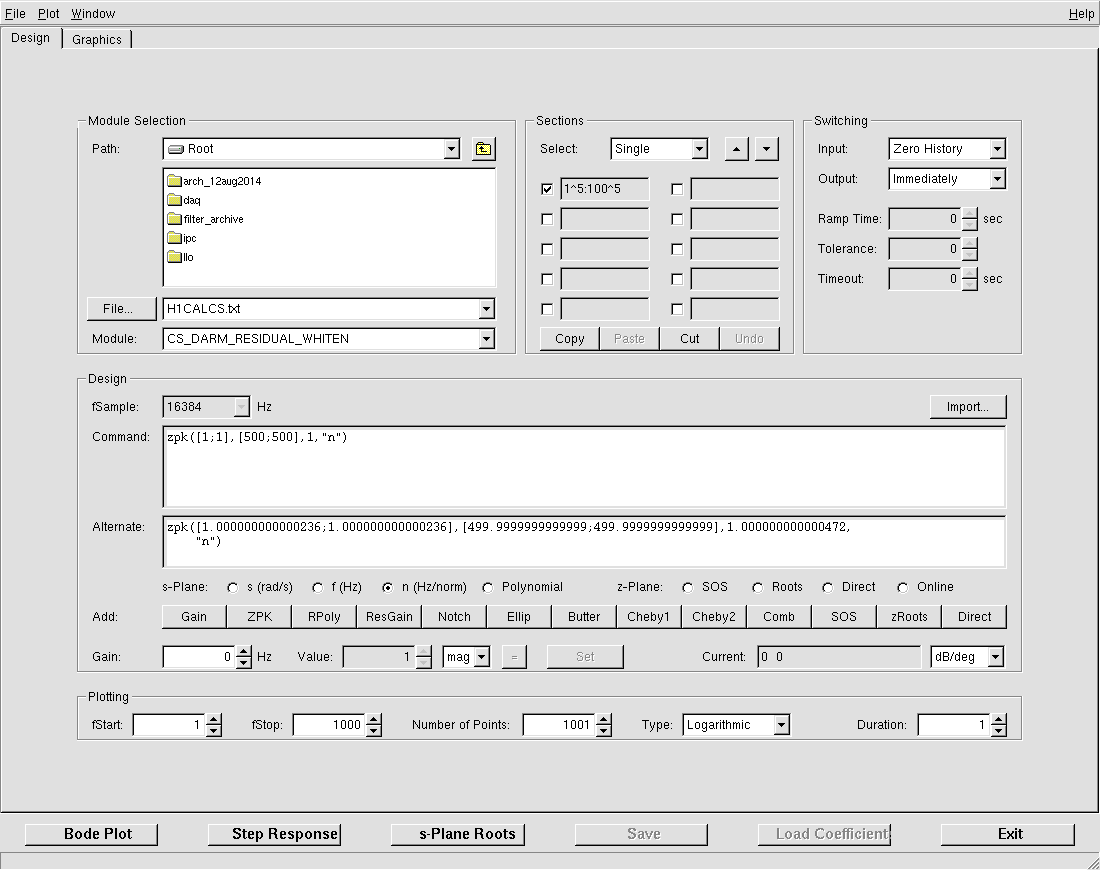
Power spectrum of H1:CAL-CS_DARM_RESIDUAL_WHITEN_OUT before applying new whitening filter plotted in "H1-CAL-CS_DARM_RESIDUAL_WHITEN_OUT_z5x1_p5x100_MAG.pdf". After applying zpk([1; 1], [500; 500], 1), the spectrum of the same channel is given in "H1-CAL-CS_DARM_RESIDUAL_WHITEN_OUT_z2x1_p2x500_MAG.pdf".
We also plan to implement similar whitening filers on new (not yet existing) channels for Delta L_{TST} and Delta L_{PUM/UIM}.

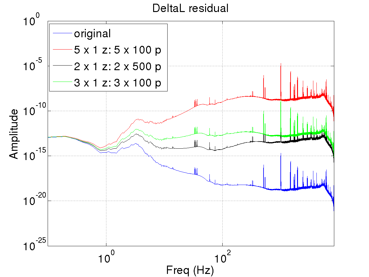
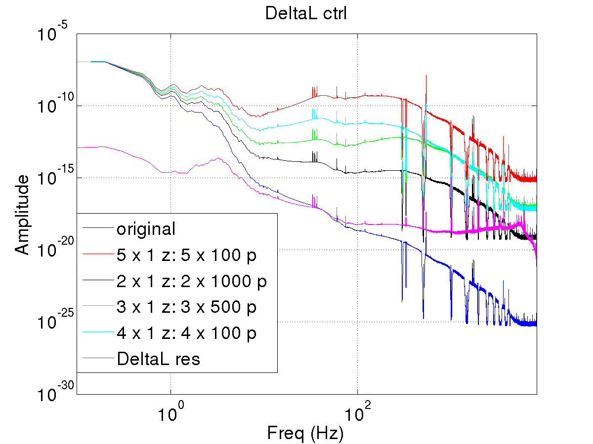
Below are plots showing the effect of differnet whitening filters including the one that was being used unitl now (5 x 1Hz zeros and 5 x 100 hz poles). These plots are the basis for new filters for DeltaL residual and DeltaL control. In those plots blue curve corresponds to actual data and other colors represent different whitening filters applied to the data.
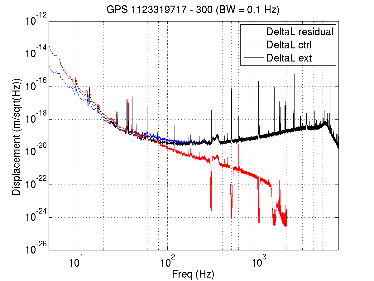
With the new filters installed we looked at the DeltaL residual and DeltaL control during a recent lock. Below we have attached the spectrum of both along with DeltaL external as a reference (which is still being used with old 5 x 1 Hz zeros and 5 x 100 Hz pole filter). In the plot the channels are dewhitened with the corresponding filters.