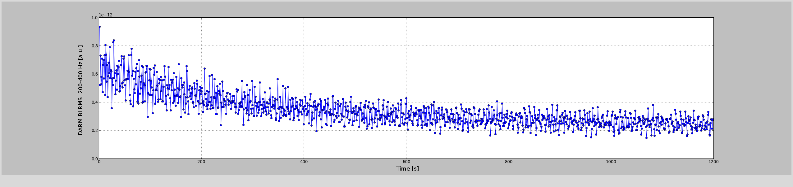
I alrady noticed yesterday that the DARM noise at the periscope peaks (200-400 Hz) was high at the beginning of the lock and then reduced over time.
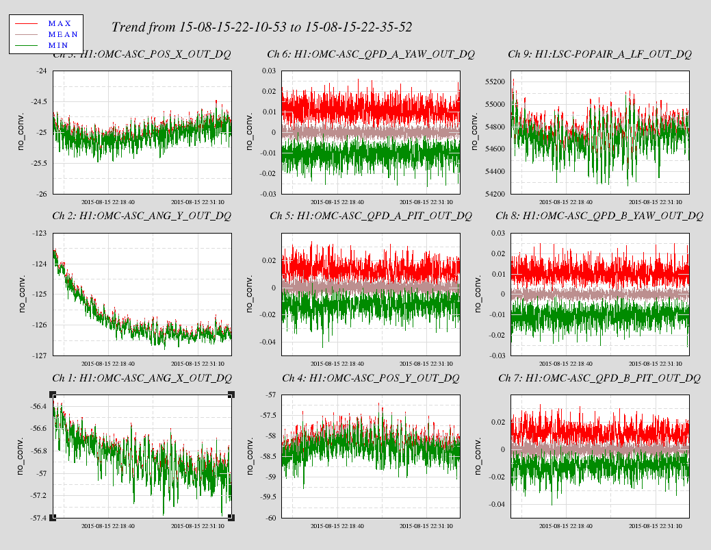
The first attached plot shows a BLRMS of DARM around those peaks, starting right after reaching the low noise state. There is a clear reduction of the noise over time. The second plot shows that on a similar time scale, the OMC alignment output signal changed, mostly ANG_Y.
This seems to confirm the idea that input beam jitter at the periscope peaks is converted into intensity noise by an OMC misalignment, which changes over time.
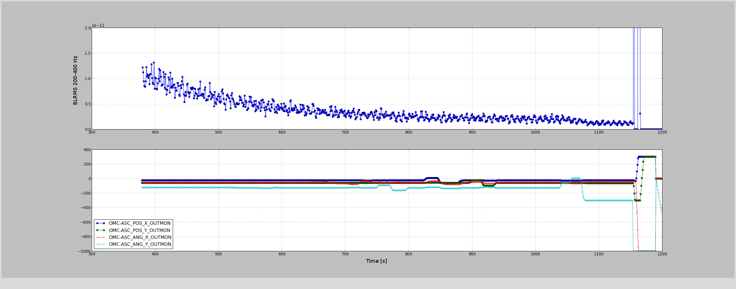
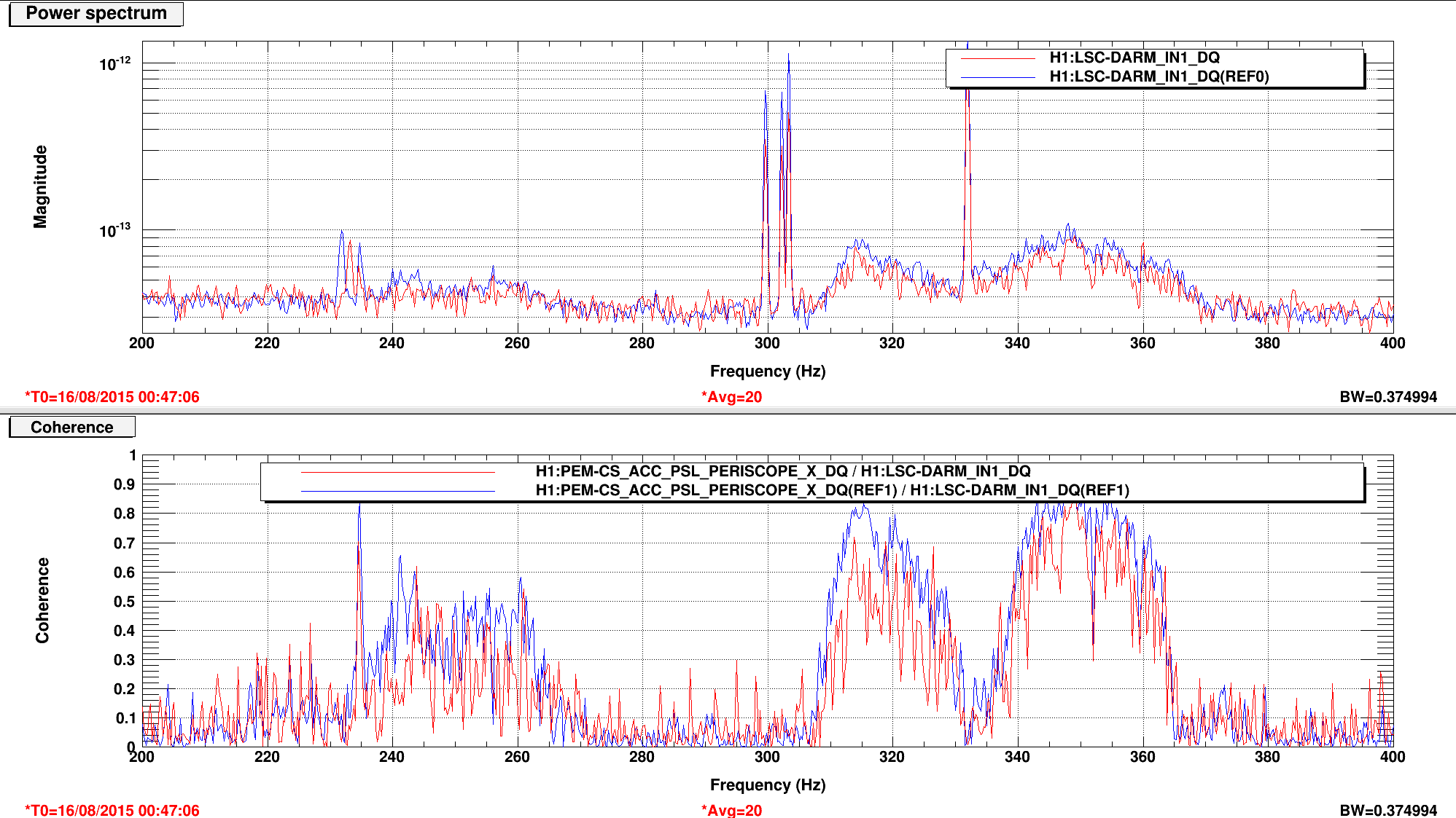
To confirm this, I move the OMC angular loops during full lock, adding offsets of few tens of counts to the POS and ANG loops. The third plot shows the steps in the control signals. I was able to reduce the BLRMS by adding an offset of -40 to the ANG_Y loop. The fourth plot compares the DARM spectrum with (red) and without (blue) the ANG_Y offset. I should have increased the offset more. Unfortunately, I noticed that the output was hitting the limit of 300 and I stupidly increased it to 1000: but since the loop was integrating, I broke the lock since I suddenly increased the output from -300 to -1000.
However, the experiment confirms that the noise at the periscope peaks changes in amplitude with the OMC alignment, which is not optimal.
I am not 100% sure what value Gabriele meant to leave, but I have accepted in SDF (Sheila and I are in process of clearing a bunch of diffs in SDF) the value of -30 for ANG_Y for the OMC. I'll check with Gabriele about what value he meant to leave (his alog seems to indicate -40, but we found it at -30).
Since we're using the QPD loops to align the OMC, it's probably better to record any change in the alignment in the QPD offsets. I forget the channel names at the moment, but these are the offsets in the OMC QPD channels (not the same channels in the ASC models). If the offsets are stored in the ANG and POS loops, they will have to be turned off if/when we switch to the dither alignment. If they are recorded in the QPD filter banks it is one less thing to think about.
To summarize the OMC alignment: the QPD offsets have been tuned so the OMC is well-aligned in the low power state. In this state, the dither error signals should be zero. We know that as the power is increased, the QPD offsets are no longer a good alignment, especially in pitch -- this is according to the dither error signals. We suspect the misalignment is due to some junk light that shifts the nominal alignment position on the QPDs. Unfortunately, the misalignment is large enough that engaging the dither loops in the high power state saturates the drive to the OMC SUS. This is why we have stuck with the QPD alignment for now...we should find a solution before O1 that allows us to use the dither loops. The last time the alignment scheme had any attention was in late May.
Needless to say, do remember to check the drives to the OMC SUS OSEMs when changing the alignment settings, they may saturate!
The offsets I left (-30) is better than 0, but not the optimal one yet. It's better to check the OMC alignment again