Daniel, Dan, Evan
Summary
We took another measurement of 45 MHz oscillator frequency noise into DARM.
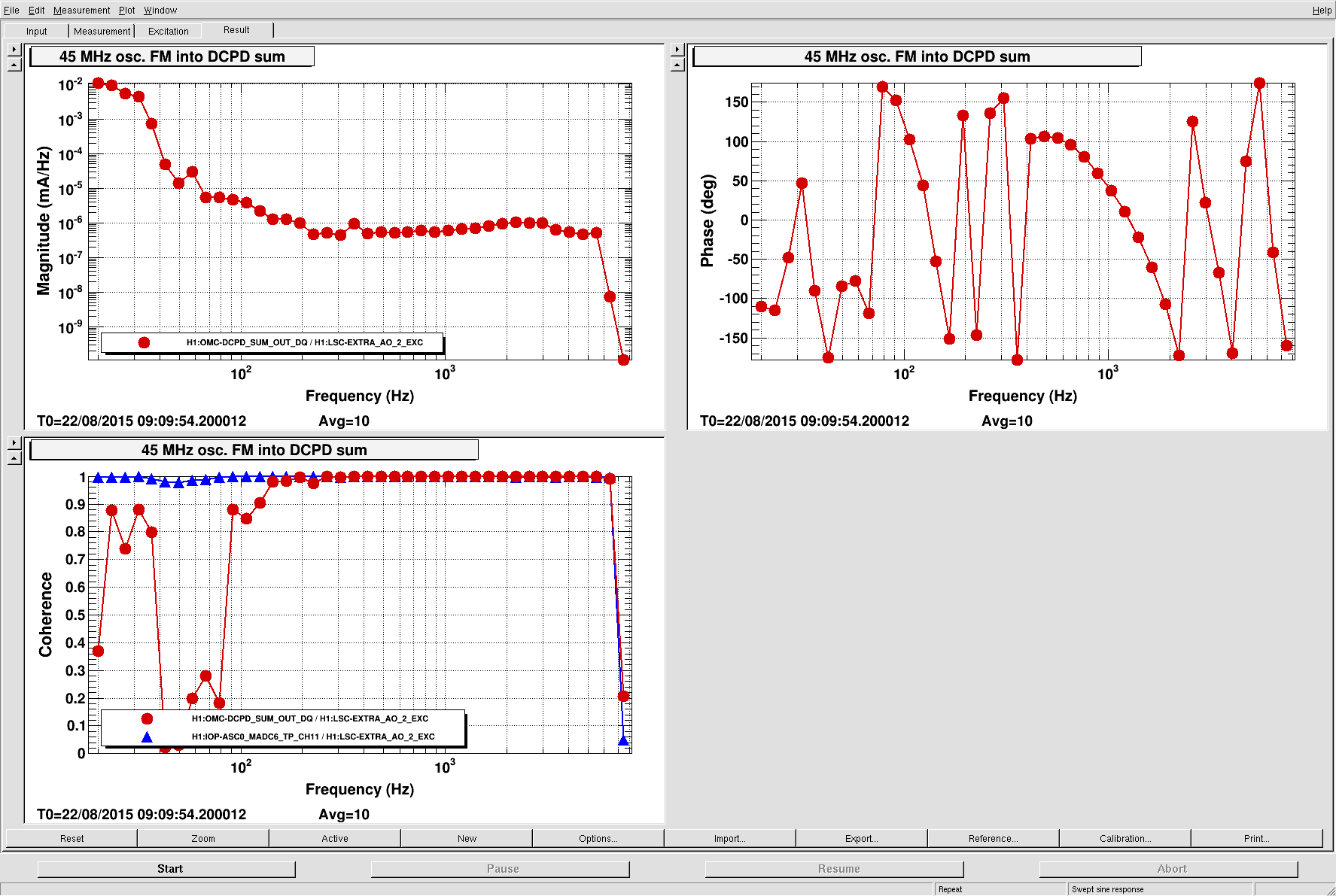
The conclusions are as follows: (1) like the previous measurement, the transfer function is flat in terms of frequency noise coupling into DCPD current, but (2) the coupling is about 7×10⁻⁷ mA/Hz, which is 5 to 6 times lower than the previous measurement. Assuming a flat 45 MHz phase noise of 4×10⁻⁷ rad/Hz1/2, we expect a contribution in the DCPD sum that is 3×10⁻¹⁰ Hz/Hz1/2 and rising like f, which is not enough to explain the excess we see (and isn't the right shape).
In the previous measurement, we had some trouble with the calibration (namely, the voltage-to-frequency coefficient on the IFR front panel didn't match what we measured with a mixer), and also we were shaking the 9 MHz and 45 MHz sideband phases simultaneously. So I am more inclined to believe this measurement.
Details
- First we wanted to measure the relative delay of the 9 MHz and 45 MHz sidebands using the nominal (OCXO/HG) configuration, so that we could preserve this phase when switching to the IFR. On a scope we saw that the crest of the 45 MHz lagged behind the 9 MHz crest by 12.8(4) ns. [Of course, this is cable-length dependent and has no absolute meaning.]
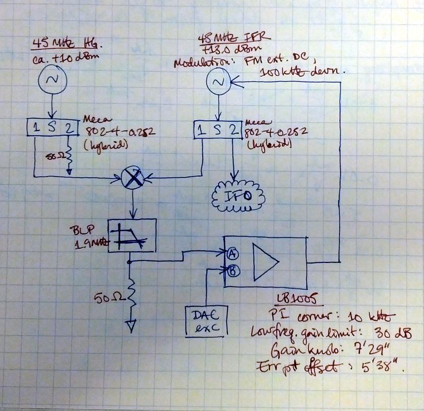
- Then we set up a PLL as shown in the attached diagram. We lock an IFR to the 45 MHz output of the HG and use this output to generate the 45 MHz signals for the interferometer. This PLL has a ugf of 46 kHz or so. By 7 kHz it has 20+ dB of loop suppression, so for the rest of this analysis we don't correct for the loop gain.
- We calibrated the PLL drive by tuning the error point offset knob on the LB1005 and watching the relative delay between the 45 MHz drives of the IFR and the HG. From this, we measured that the calibration at the error point is 45 mV/ns, which is 0.16 V/rad.
- Then using the same cable lengths as in the first step, we looked at the of the 9 MHz (from the OCXO) and the 45 MHz (from the IFR) on a scope and tuned the error point offset to give an identical delay as before.
- Then we hooked up the spare LSC DAC channel to the unused ("B") error-point input of the LB1005. The SFM for this channel is calibrated so that the excitation is in volts. We verified this in the CER with a scope. [The calibration uses FM1, which is a flat gain of 3276.8 ct/ct, along with a factor of 2 in the SFM gain. We're not sure why we need this factor of 2 to get the right calibration, since we think the calibration should be 216 ct / 20 V = 3276.8 ct/V.]
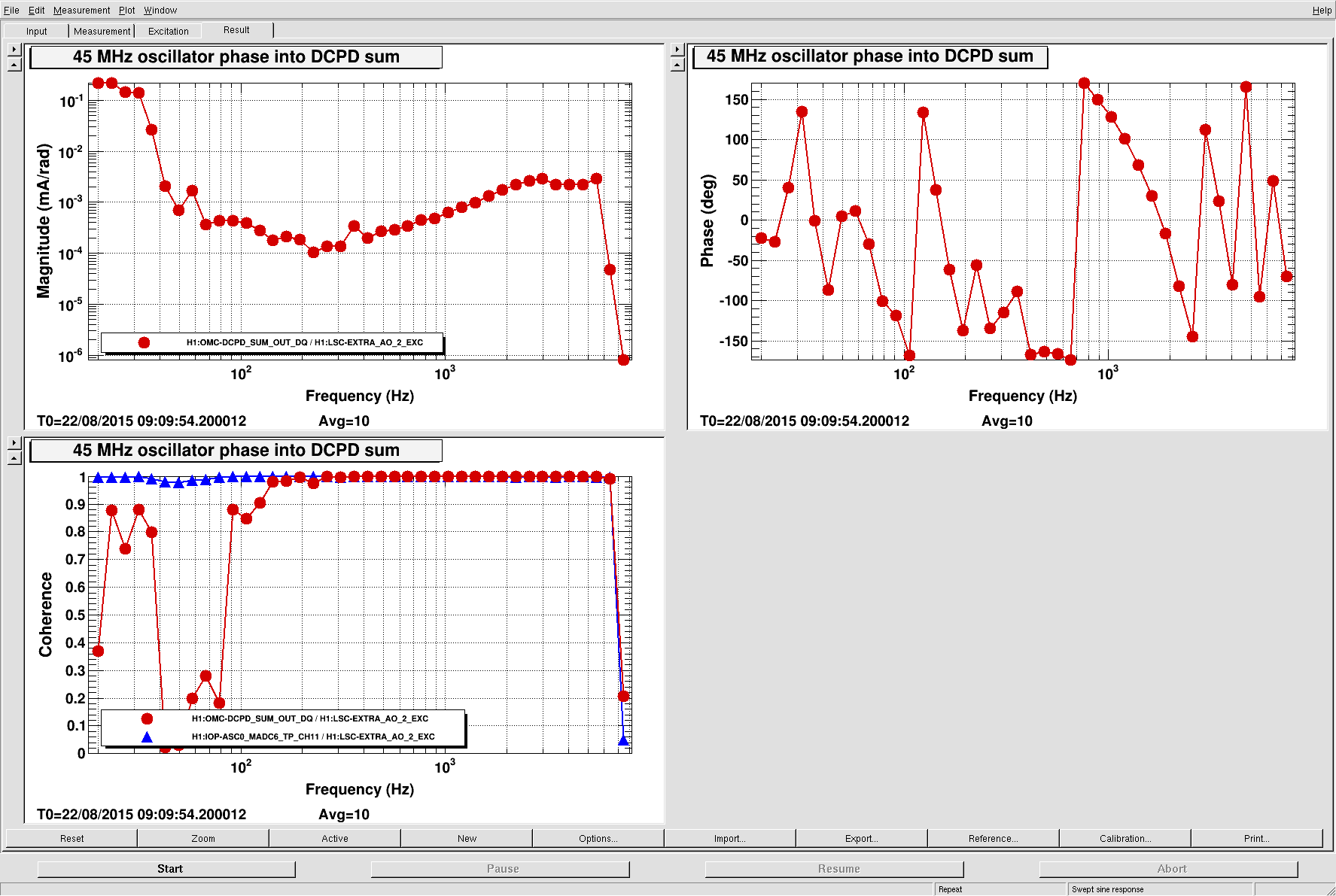
- Then we relocked the interferometer and measured the transfer function from the LSC DAC channel into the DCPD sum.
The attachments show the calibrated transfer function (both in terms of phase noise and frequency noise).