JeffreyK, Kiwamu, Darkhan
Overview
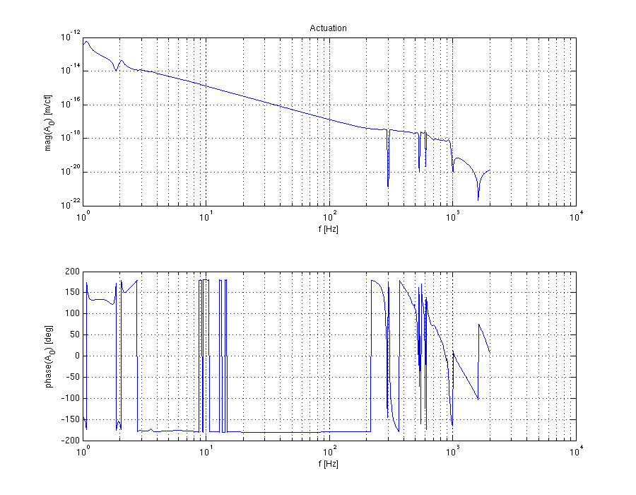
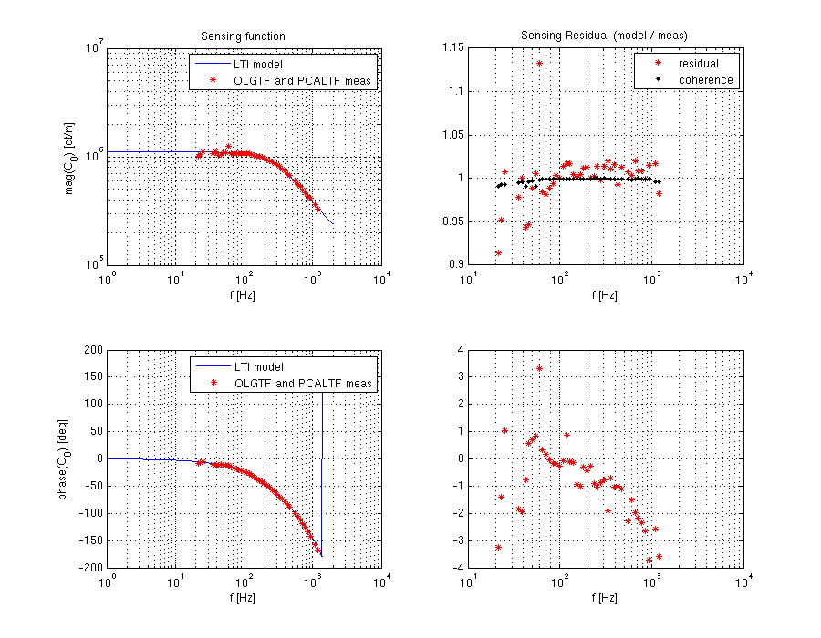
A DARM OLG TF model and its parts, sensing and actuation functions, are used for calculating the interferometer strain, h(t), and estimation of uncertainty in reported h(t).
On last Thursday we put together a DARM OLGTF Matlab model for ER8/O1 and compared it to a DARM OLGTF measurement taken on Aug 17, 2015. This model is mainly based on a similar model for ER7 (LHO alog 18769). Currently the model agrees with the measurement to only about +/-10% in magnitude and +/- 5 deg up to 200 Hz. So there's still work need to be done, probably changing parameter file needs some fine tuning of possibly following parameters: optical gain, CC pole frequency, ESD zeros and poles, ESD gain.
Details
Please, see a summary of things to be aware of when using this model (mostly listed differences from ER7 model):
-
The following parameters at this point were fit by eye:
- optical gain: 1.6*10^6
- CC pole frequency: 338 Hz
- ESD gain was adjusted by factor of 1.4
- moved ESD driver pole to 138 Hz (not sure if this helped significantly)
- One major difference from ER7 model is that the new model generates all of the frequency dependent transfer functions in the form of LTI objects (zpk, ss, sos). This should make it more convenient to obtain frequency response of DARM parameters at a desired frequency vector.
-
In ER7 time delays have been included only into overall OLGTF, but not into C, D and A. In ER8 model we explicitly included time delays at the places where they occur, i.e. SUS computation delay is included into discrete frequency response of SUS digital filters, total IOP downsampling TFs in C and A include their respective computation time delays, etc. E.g. below you can see the difference when comparing calculation of OLGTF in ER7 and ER8 models:
- OLGTF from ER7 model is: G = C * D * A * time_delays
- OLGTF from ER8 model is: G = C * D * A (time delays were included into C, D and A)
- Since not all of the frequency dependent TFs that contribute to the DARM OLGTF are coming from discrete (computation) or analog/continuous (electronics, optics, mechanics) sources, but rather from mix of the two kinds, there is no a single LTI object for OLGTF (G), actuation (A) and sensing (C) functions. For user convenience this model includes inline functions that generate C, D, A and G transfer functions at a user requested frequency vector. E.g. if we want to obtain TFs in the range [10 .. 100] Hz with 1 Hz frequency resolution, following commands can be used:
[ol, par] = H1DARMmodel_ER8('par_file');
freq = 10 : 1 : 100;
G = par.G.getFreqResp_total(freq);
A = par.A.getFreqResp_total(freq); % total actuation function
% frequency responses of actuation stages can be obtained similarly
A_tst = par.A.getFreqResp_TST(freq);
% frequency responses of C with and without CC pole
C = par.C.getFreqResp_total(freq);
C_res = par.C.getFreqResp_noCavPole(freq);
- In ER7 for analog AA and AI filters both LHO and LLO sites used averaged frequency response of measurements taken at LLO. Recently Kiwamu and I processed AI filter measurements taken at LHO EY during calibration week before ER7 (LHO alog 18639), and produced a new zpk model of AA/AI filters based on these measurements (LHO alog 20769). Now we are using this new analog AA/AI model. One assumption that we are still making is that analog AA and AI filters have the same frequency response. To ensure that this assumption holds we will need to compare other AA and AI chassis measurements from pre ER7 (LHO alogs 18628, 18639) with the AA/AI model.
- In this DARM model the suspention TF is taken from a tagged suspension model that was recently created by Kiwamu and Sudarshan; this tag was also installed in calibrated Pcal RxPD and TxPD channels (LHO alog 20334).
- Another minor change is that parameter file for the measurement from 2015-08-17 uses OMC and SUS filter files that are copied into calibration SVN, this makes the scripts ready to run outside of control room.
We still need to take more DARM OLGTF and PCAL to DARM TF measurements and compare them to better estimate DARM model parameters.
The model was uploaded into calibration SVN (r1095):
CalSVN/aligocalibration/trunk/Runs/ER8/H1/Scripts/H1DARMOLGTFmodel_ER8.m
The parameter file associated with measurement taken on Aug 17 is in the same directory:
CalSVN/aligocalibration/trunk/Runs/ER8/H1/Scripts/DARMOLGTFs/H1DARMparams_1123894143.m
I believe that these scripts are in a reasonable shape to try it with LLO DARM parameters.