jeffrey.kissel@LIGO.ORG - posted 22:54, Monday 24 August 2015 - last comment - 22:59, Tuesday 01 September 2015(20846)
H1 SUS ETMY Coil ESD Drivers Measured to High Precision
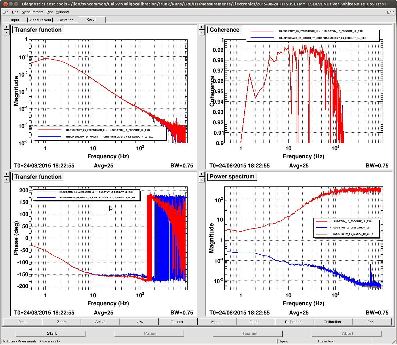
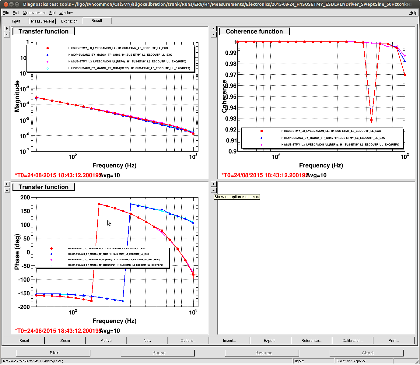
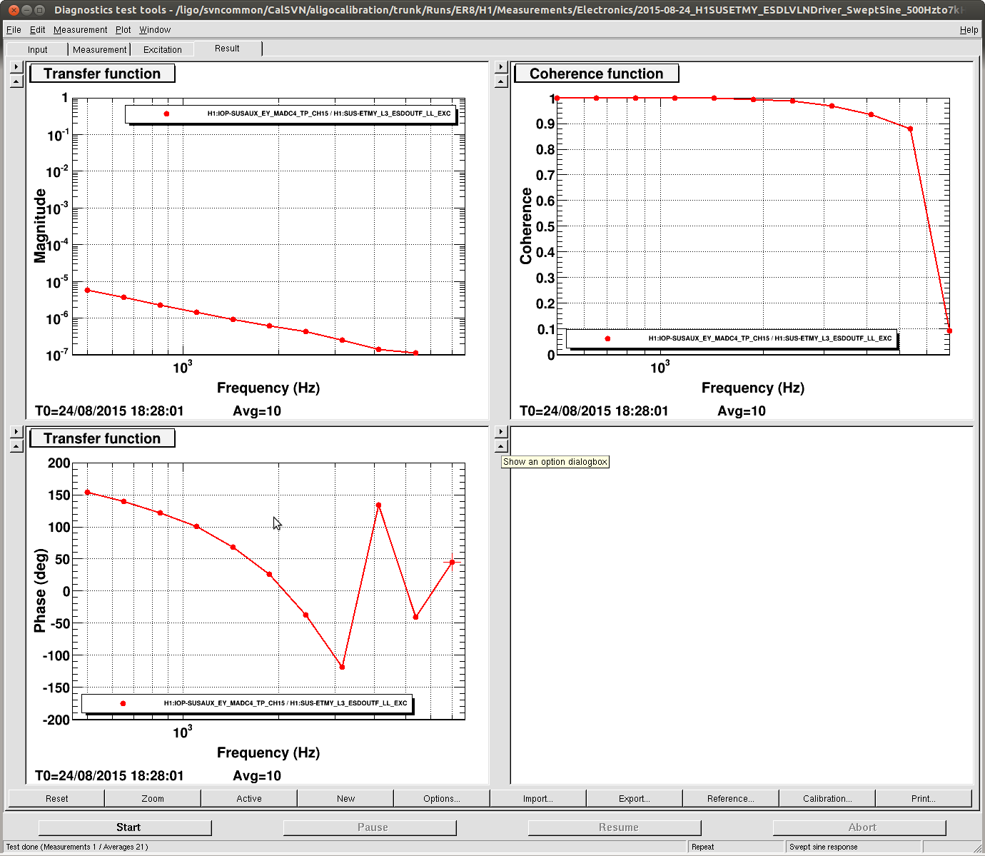
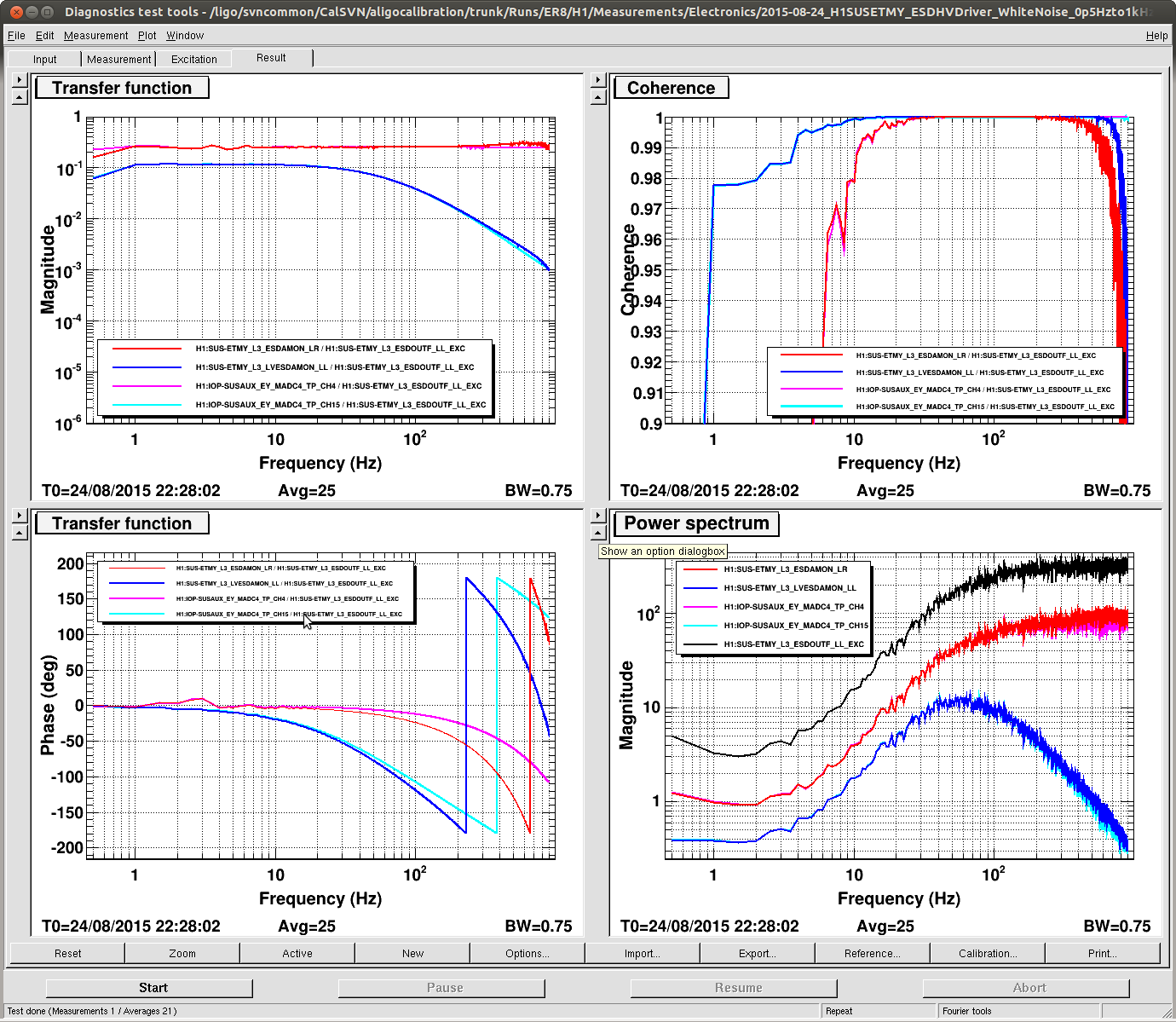
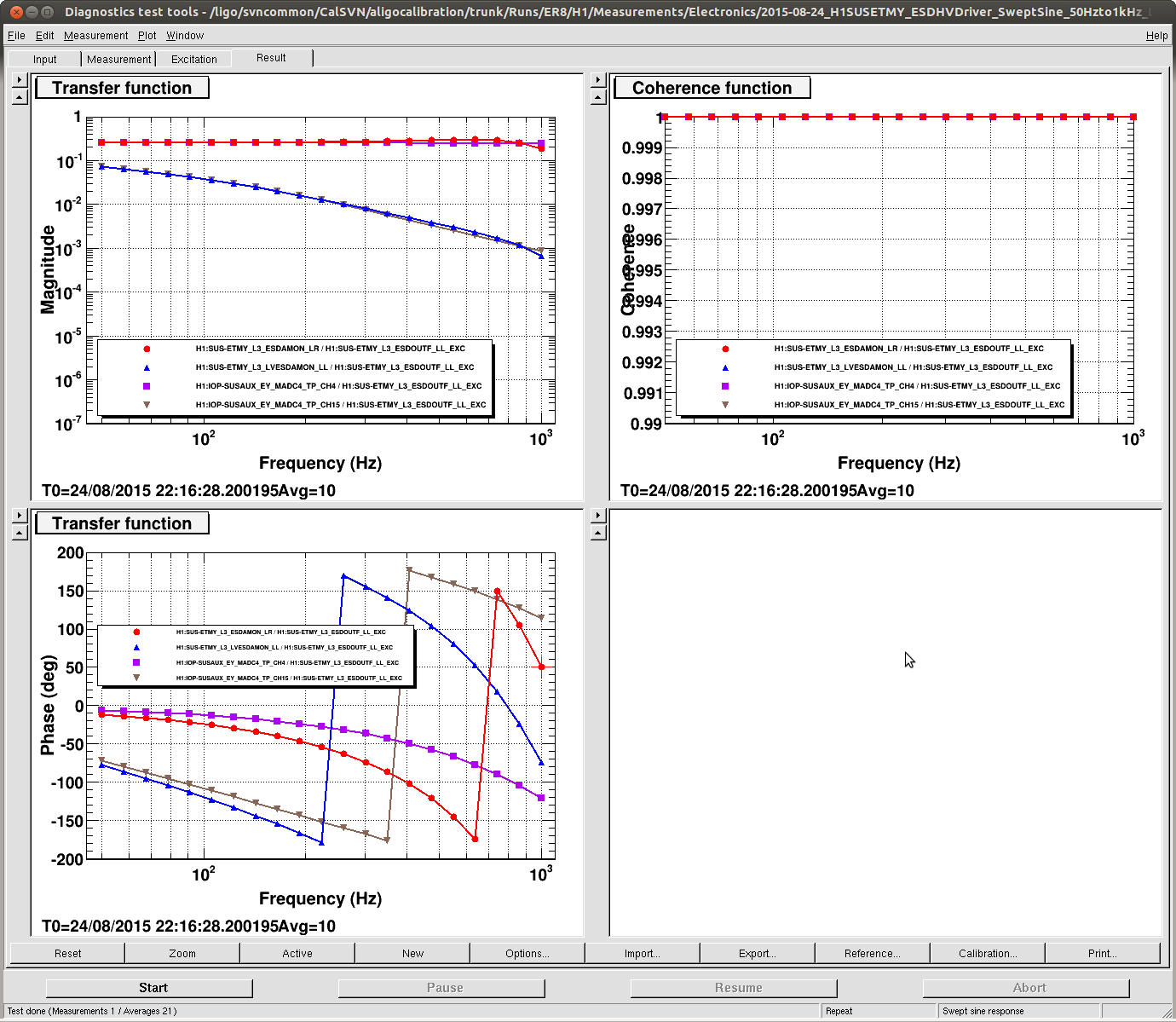
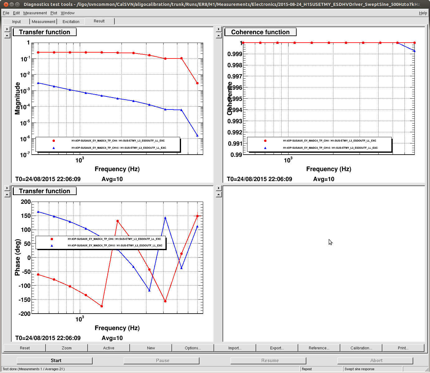
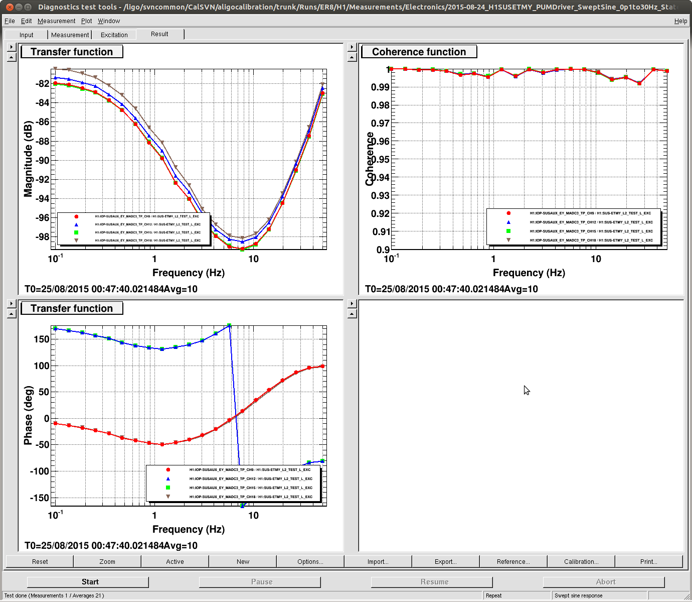
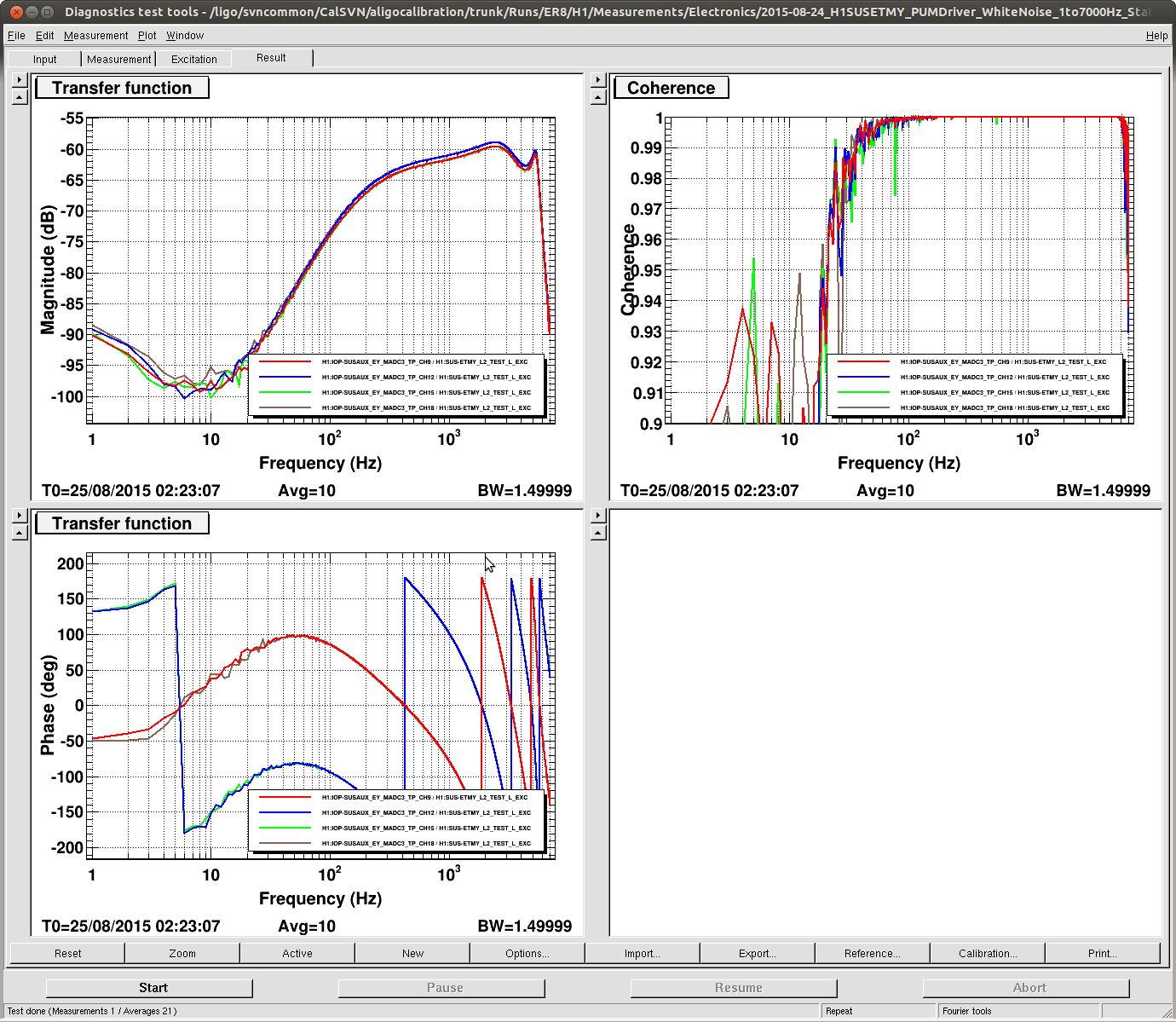
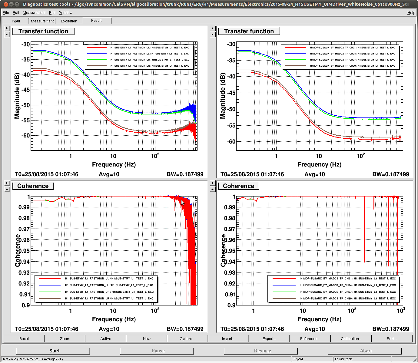
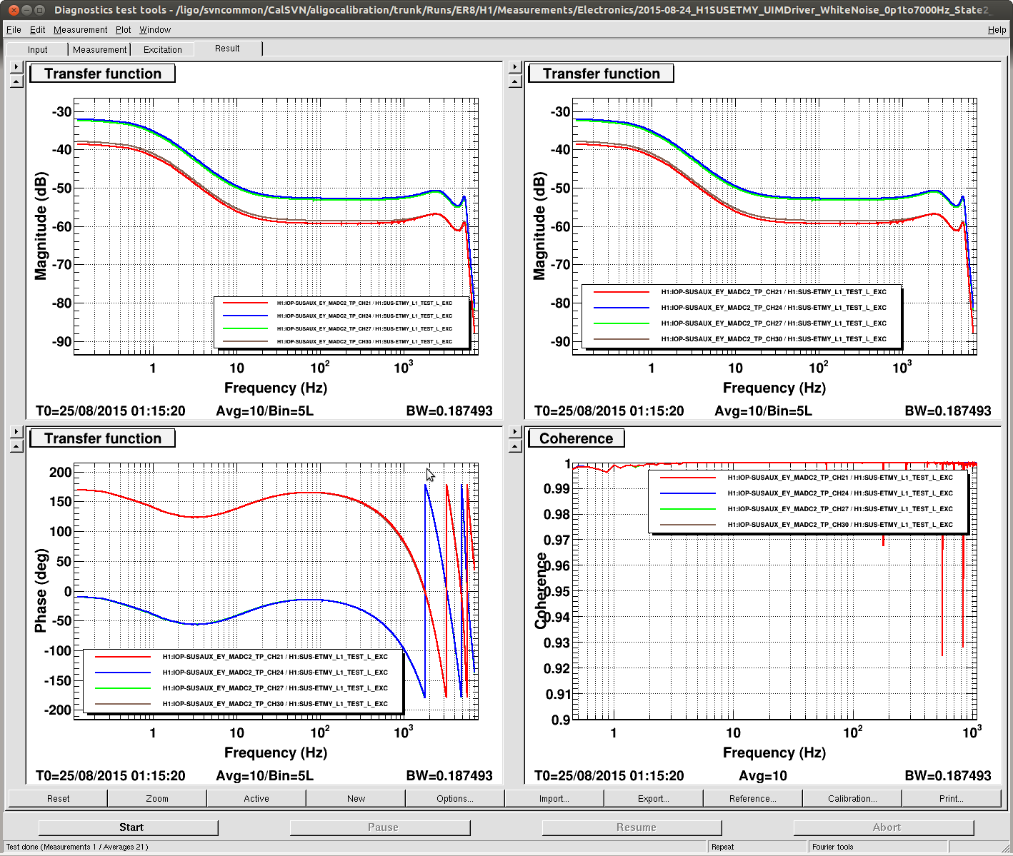
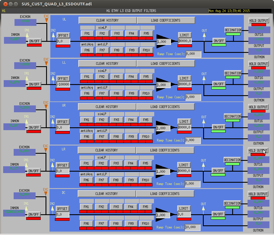
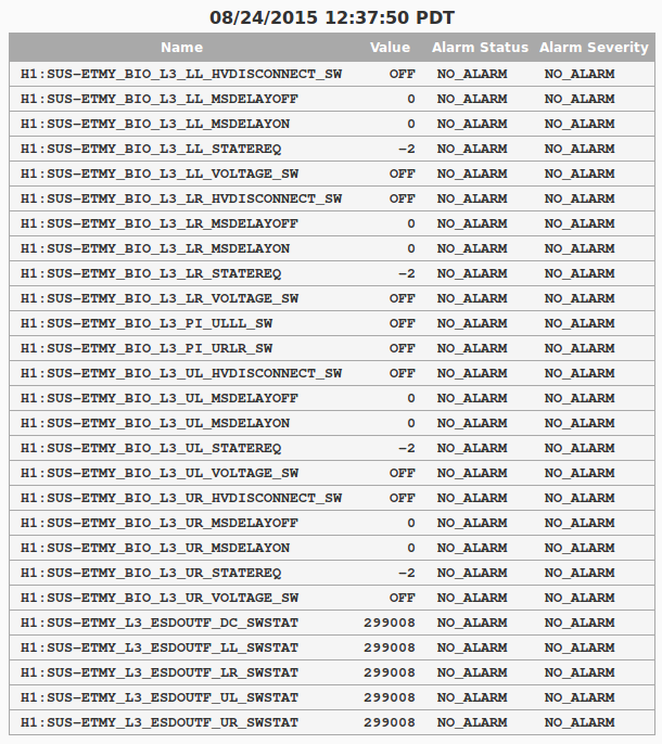
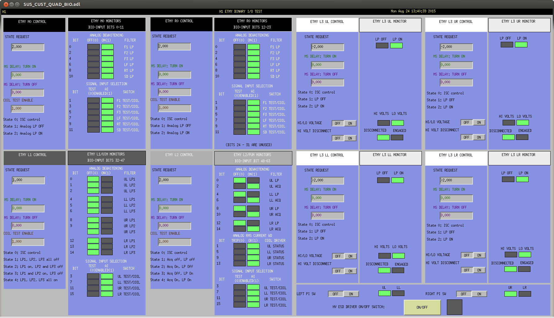
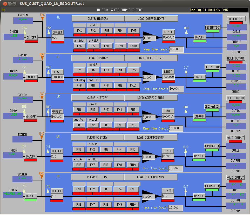
J. Kissel

For efforts of limiting systematics in the calibration, I've measured all ISC controlled stages of ETMY drivers, UIM, PUM, and TST. For now, I just attach screen shots of the measurements and report where they live, such that LLO might repeat exactly the same measurements tomorrow (instead of their current plan to take the measurements in analog, lugging around an SR785). In the fullness of time, I'll fit these to get precise poles and zeros for use in the DARM model.

I can already tell that they will be different from what has been quoted as cannon -- LLO aLOG 4495 -- which is upon what all ETM current *coil* driver compensation filters are based. For example, for some reason, the z:p = 50:300 [Hz] filter on the output impedance network of the UIM drivers, seems to have disappeared. It was supposed to have moved up in frequency when we increased the drive strength (see T1400223 and E1400164) but not disappear. It shouldn't matter for the calibrating, but this is just rediculousness that should be investigated lest we're being misinformed about the frequency region we do care about by a bogus measurement.

Anyways, I'll do a similar study to what was done in LLO aLOG 4495 with this data, and we will compensate the calibration accordingingly.

Details:
------------------
In order to
(1) speed up measurements
(2) focus drive amplitude and number of cycles in the frequency regions which were needed, and
(3) yield the ability to do multiple slow measurments simultaneously
I split the measurements for each driver into several templates with differing frequency bands. Ideally, if I weren't inventing, completing, and hoping to analyse it all to give me a very precise result in one day, I would have used the SEI group's Schroeder-phased TF tool, which has such flexibility, but alas.

The templates live and have been committed to here:
/ligo/svncommon/CalSVN/aligocalibration/trunk/Runs/ER8/H1/Measurements/Electronics/
For ESD Driver in low-noise configuration:
2015-08-24_H1SUSETMY_ESDLVLNDriver_WhiteNoise_0p5Hzto1kHz_$(QUADRANT)_TF.xml
2015-08-24_H1SUSETMY_ESDLVLNDriver_SweptSine_50Hzto1kHz_$(QUADRANT)_TF.xml
2015-08-24_H1SUSETMY_ESDLVLNDriver_SweptSine_500Hzto7kHz_$(QUADRANT)_TF.xml

For ESD Driver in high-range configuration:
2015-08-24_H1SUSETMY_ESDHVDriver_WhiteNoise_0p5Hzto1kHz_$(QUADRANT)_TF.xml
2015-08-24_H1SUSETMY_ESDHVDriver_SweptSine_50Hzto1kHz_$(QUADRANT)_TF.xml
2015-08-24_H1SUSETMY_ESDHVDriver_SweptSine_500Hzto7kHz_$(QUADRANT)_TF.xml

For PUM Driver (each template covers all quadrants)
2015-08-24_H1SUSETMY_PUMDriver_SweptSine_0p1to30Hz_$(FILTERSTATE)_TF.xml
2015-08-24_H1SUSETMY_PUMDriver_WhiteNoise_1to7000Hz_$(FILTERSTATE)_TF.xml

For UIM Driver (each template covers all quadrants)
2015-08-24_H1SUSETMY_UIMDriver_WhiteNoise_0p1to900Hz_$(FILTERSTATE)_TF.xml
2015-08-24_H1SUSETMY_UIMDriver_WhiteNoise_0p1to7000Hz_$(FILTERSTATE)_TF.xml

Regarding the system set-up, I took advantage of the secret coil driver switching ability (revealed in, for example, on page 8 of G1401184), to turn off the digital compensation filters, and drove through the either the ESDOUTF bank for L3/ESD or the TEST bank for L1 and L2. Note, though I turned off the frequency dependent compensation, I did not turn off any of the OUTF gain and sign compensation (which is why some of the PUM and UIM driver's signs are flipped with respect to each other). I'll take this into account during post-processing.

Also, I've used the 65 [kHz] IOP test point SUS AUX monitor channels as my response channels. I discovered all too quickly that we've been running all of our AUX monitor models at 2048 [Hz].  Sadly, because we ('ve been told we) must develop a very precise inverse actuation filter for the hardware injection team, we need to get information about the high (but not super-nyquist) frequency poles which we compensate for in the DARM ESD path (namely, the ~3250 [Hz] zero -- see LHO aLOG 18769 and LHO aLOG 18579). Not only does a sampling rate of 2048 prevent measuring such zeros, there's also severe distortion from the 65 [kHz] to 2 [kHz] very aggressive IOP down sampling filter. Yes, we know the shape, but it's just much less confusing to not include it in the measurement. However, comparing the IOP test points against the user model versions of the channels did provide good sanity checks. It for example allowed me to identify that -- even though we fixed the user-model channel ordering of the monitors for the low-noise driver, we haven't yet fixed them for the high-voltage monitors, so the Lefts are still reversed from the Rights.
Images attached to this report

Comments related to this report
More on this screwy UIM driver result:

I've quickly processed the measurement, just to better show the world that this UIM driver is totally confusing.

Again, the measurement is from the TEST L bank (otherwise empty, gain of 1.0) of the UIM to the IOP Channel of the FAST I MON. During the measurement, all digital compensation of poles and zeros are OFF. This means the signal chain of the measurement is
Drive [ct] >
    Euler2OSEM Matrix Element (E2O) >
        Coil Balancing Gain (CBG) >
            IOP 16k-65k AI(f) >
                DAC [V/ct] (G_{DAC}) >
                    Analog AI(f) [V/V] >
                        Coil Driver [A/V] >
                            FAST I Monitor Board [V/A] >
                                Analog AA(f) [V/V] >
                                    ADC [ct/V] (G_{DAC})>
                                        IOP Response [ct]
That means, to calibrate this measurement of (IOP Response [ct] / Drive [ct]) into the [A/V] of the coil driver, I must divide out the frequency response one 16k-65k IOP upsampling or "AI" filter, the two identical analog AA and AI filters, and multiply by the following gains,

                  R24_{MON}       1                   1     1       1               [ A/V ]
DC calibration  = --------- x ---------- x G_{ADC} x --- x --- x ------- = 0.024954 -------
                  R25_{MON}   2 R5_{UIM}             E2O   CBG   G_{DAC}            [ct/ct]

where the response is calibrated with R24_{MON} (= R27 = R29 = R33) = 30k [Ohm] and R25_{MON} (= R35) = 10k [Ohm] which are the gain resistors on the differential-to-single-ended amplifier on the fast current monitor on the monitor board (D070480), coupled with the output impedance of the UIM driver R5_{UIM} (= R23) = 2000 (D070481, with the more up-to-date T1400223), a factor of two from the current monitor math, and G_{ADC} = 40[V] / 2^16 [ct]. For the drive, the Euler-to-OSEM matrix element E20 = 0.25, the coil balancing gain for UL = 0.957, and the gain of the DAC, G_{DAC} = 20 [V] / 2^18 [ct].

With the above calibration, I get the attached plot. I show the UIM's UL coil (the magnitude shows the same response for all four coils).

Where we expect the C12, R104, R4, and R5 output impedance network in the UIM driver D070481 to yield a zero:pole pair of (now) 85:300 [Hz] that is a default frequency response in all states, we see none. State 1, where all low pass filters are OFF, makes this dreadfully obvious.

Even worse, with the DC gain calibration as described above, I do not reach the nominal 0.62 [mA/V] that T1400223 claims either, I get 0.28 [mA/V].

Gross!

If the H1-SUS Rack DCC file card for ETMY is up-to-date (S1301920), the serial number of this chassis is S0900304. This is consistent with the modification aLOG LHO aLOG 11514. Unfortunately, though the traveler was updated, the test plan is just a copy-and-paste of the acceptance testing prior to modification.

When the oppurtunity strikes, I'm going to take measurements of the other UIM drivers to confirm that I'm not insane.
Non-image files attached to this comment
