hugh.radkins@LIGO.ORG - posted 12:29, Monday 31 August 2015 (21052)
Revisit Tidal Offset to HEPI Bleed down Rate reduction
re aLOG 20296, the bleed off of the tidal drive to the HEPIs tilts the platform enough to rile up the ISI T240s. Looked at trends for the last 30 days; the bleed down rate changed from 2 to 1u/s on 6 August.
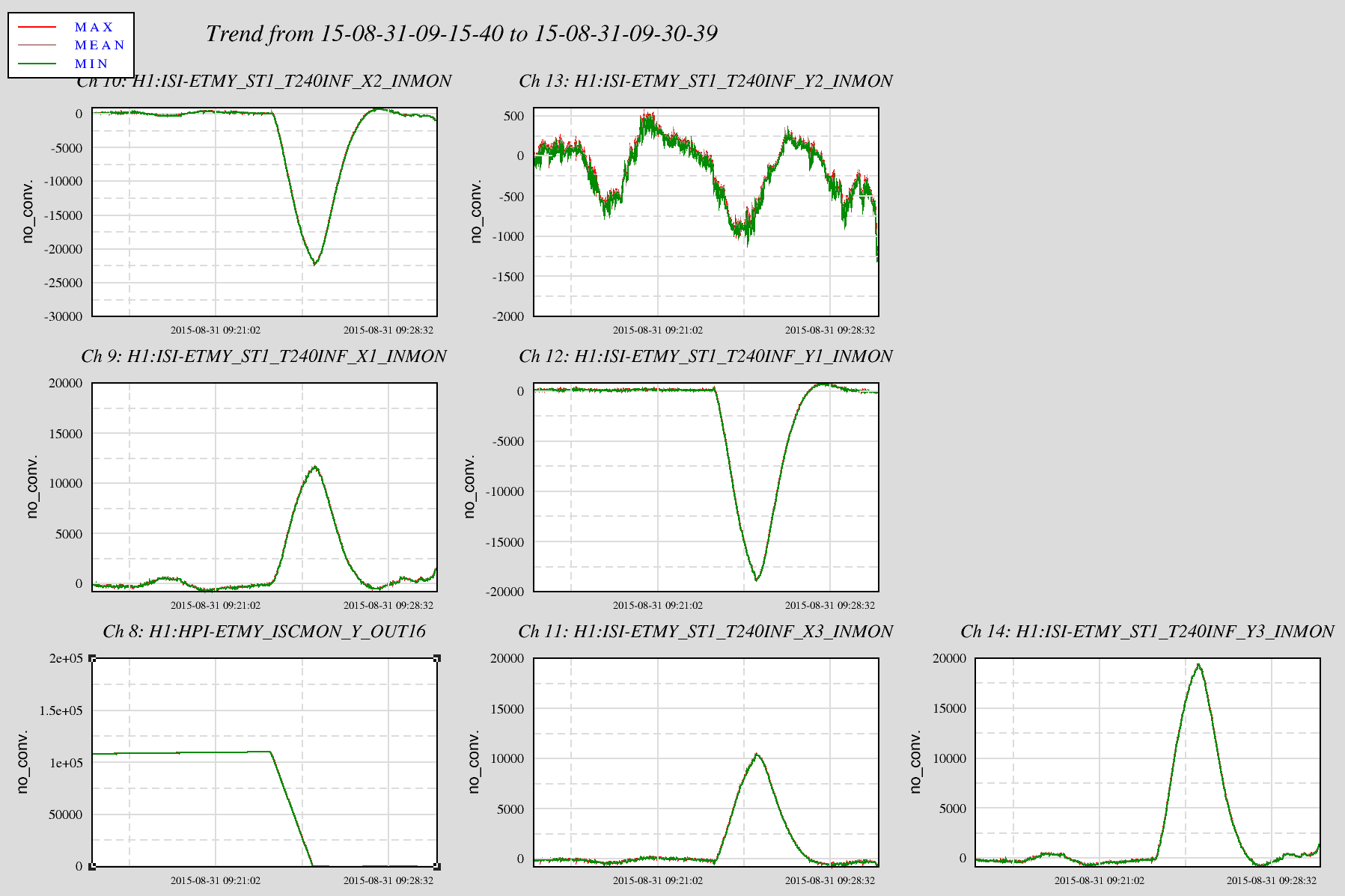
Since then there have been many lock losses where there was some tidal buildup to be bled off. The diagonalization of the EndX HEPI must be pretty good and gives no indication of tilting the T240 much. Unlike X, the HEPI for EndY shows some fairly substantial tilting as the build up is reduced. See the attached for 15 minute plot of a recent Bleed off at EndY where the ~110um bleed off at 1u/s riled up the T240s more than half way to the trip point.
The EndY HEPI could use some diagonalization
Images attached to this report