Highly related: alog 21234
Conversion coefficients to obtain the equivalent beam rotation at the periscope from IMC WFS signals were measured at around 20Hz while IFO was operating in low noise (see subentry for details):
| PIT (nrad/ct) | YAW (nrad/ct) | |
| IMCWFSA | 5.8 | 4.6 |
| IMCWFSB | 3.5 | 1.4 |
There could easily be 10 or 20% error but this cannot be off by an order of magnitude.
Note that the PIT to YAW and YAW to PIT coupling in the sensing are not small at all. PIT to YAW sensing coupling is about 0.6 for WFSA and 0.9 for WFSA, while for YAW to PIT the numbers are 0.5 for WFSA and 0.4 for WFSB. (This is not surprising as the WFS quadrant gains are fishy: alog 20065). If we need to evaluate PIT and YAW jitter separately, it's somewhat better to use WFSB for PIT and WFSA for YAW.
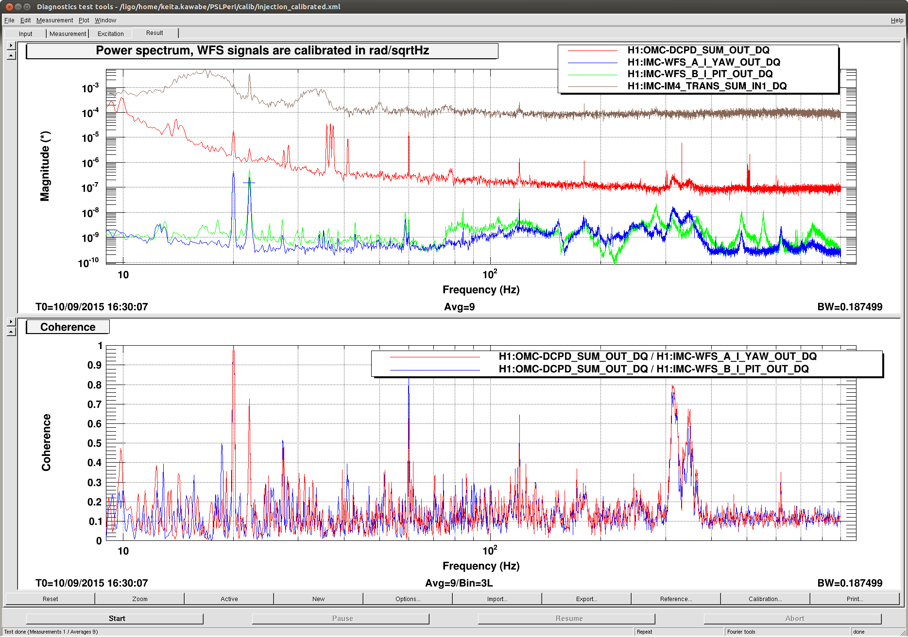
The attached shows WFSB PIT and WFSA YAW, already calibrated to radians using the above table (assuming that WFS response as a sensor is flat), and OMC DCPD in full lock. There are two lines injected to Peri PZT, @20Hz for YAW and 22.1Hz for PIT. The excitation voltage is the same for both, but due to the fact that peri mirror is tilted by 45degrees in PIT, beam deflection in YAW is sqrt(2) smaller than PIT.
Taking this into account, PIT to DCPD coupling is a factor of 7.5 smaller than YAW coupling. Looking at the peaks, indeed there are peaks in WFSB PIT, most notably at 280Hz, that are not present in DCPD even though the hight was as large as annoying twin peaks at 315 and 350Hz, and this is consistent with the smaller PIT coupling.
The attached also shows IMC trans SUM. PIT peak (22.1Hz) is much larger than YAW (20Hz) even you take a factor of sqrt(2) into account. This is probably due to the fact that MC WFS offset for PIT is much larger than YAW. Even then, PIT coupling is smaller. This is one of several things that show that this cannot be a simple jitter AM conversion by MC.
Among many calculations that could be done, I'll probably convert the input beam jitter to the beam jitter on OMC.
How the WFS calibration numbers are obtained:
1. PZT sensitivity in rad/volt
The PZT is PI S-330.4 type (T1500342). The controller is PI E-616.SS0G which has -2 to 12V input range in open loop mode. This combination gives 7 mrad p-p tilt in both axes (E1300470).
So this is about 7mrad/14V(drive input) at DC.
2. Beam rotation at the PZT mirror
The PZT is tilted 45degrees in PIT. This doesn't affect the beam rotation per mirror tilt for PIT (beam angle = 2* mirror tilt), but does make it sqrt(2) smaller for YAW.
3. DAC to driver input
According to Vern our 16bit DAC gives +20V differential maximum and -20V differential minimum. According to D1100909, AI output goes to D1100482 and then to the driver (note that LPF is ommitted in D1100909 but should be added).
It seems that there's no DC gain in D1100482 (D1100457 inside, the board converts +-20V differential to +-20V single ended though the output should rail at the supply voltage).
drive input/DAC count = 40V/2^16 = 610uV/cout.
4. LPF (alog 21300)
Pole is at about 1.2Hz. This was confirmed by injecting lines at around 0.1Hz, 1Hz and 20Hz for YAW and looking at IMC WFS DC when MC2 was misaligned (not shown here but the file is /ligo/home/keita.kawabe/PSLPeri/calib/WFSDCcalib2Y.xml).
No reason to believe that this is any different for PIT.
5. Injection into PZT at 20Hz for YAW and 22.1Hz for PIT in full lock
At 20Hz I assume that the effect of the IMC ASC is small even at 20W. I measured the TF from injection to the WFS outputs (the file is /ligo/home/keita.kawabe/PSLPeri/calib/injection.xml).
PZT PIT PZT YAW
WFSA P 5.6 2.5
WFSA Y 3.2 5.5
WFSB P 9.4 7.4
WFSB Y 8.9 18.3
(Note that PIT to YAW and YAW to PIT coupling numbers in the parent log were obtained from this.)
6. Combining numbers
From 1 to 4, beam rotation per DAC count is 0.6/(1+i*f/1.2Hz) urad/ct for PIT, 0.4/(1+i*f/1.2Hz) urad/ct for YAW, i.e. 33nrad/ct for PIT and 25nrad/ct for YAW at injection frequencies.
I divide 33nrad/ct by e.g. 5.6 to obtain the conversion coefficient for WFSA PIT.
Paul has done some measurements in the past to misalign the MC to assess the jitter noise in calibrated units. I wonder if his results agree with the calibrated WFS error signals.