Dan, Travis
Following up on the measurement of the tip-tilt response at high frequencies, I've moved the OMC alignment dither lines up above 2kHz. The new frequencies are [2125.1, 2150.1, 2175.1, 2200.1] Hz. The amplitudes were slightly increased to maintain the same line height after the reduction in the tip-tilt response at high frequency. In the filter banks following the demodulation, I changed the frequencies of the elliptic filters that are used to notch the line frequencies post-demodulation.
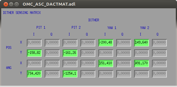
To update the control scheme, I adjusted the phase rotation of the demodulated signals such that offsets in the alignment loops only showed up in the I phase signals. Striptools are the best way to do this. Then, I reran the ditherDCsense script to calculate a new sensing matrix, and closed the loops. Things looked pretty stable, so let's stick with this new arrangement. I attach a screenshot of the new sensing matrix.
If for some reason people get spooked and want to revert, do the following:
- set the frequencies back to what they were before: [P1, P2, Y1, Y2] --> [1675.1, 1700.1, 1725.1, 1750.1]
- set the oscillator CLK_GAINs to 100. The current CLK_GAINs are [150, 120, 100, 130].
- in the dither demodulation, for filter banks {P,Y}{1,2}_X_{SIN,COS}, switch from FM7,9 to FM8,10. These are pairs of ELPs that notch the dither line in the demodulated signal. They're used to squash high-frequency stuff from the control signal. It's probably excessive.
- set the R demod phases to 90. They are currently 135, 150, 150, and zero.
- use conlog to revert the sensing matrix. Look for changes to channels of the form "H1:OMC-ASC_DACTMAT*".
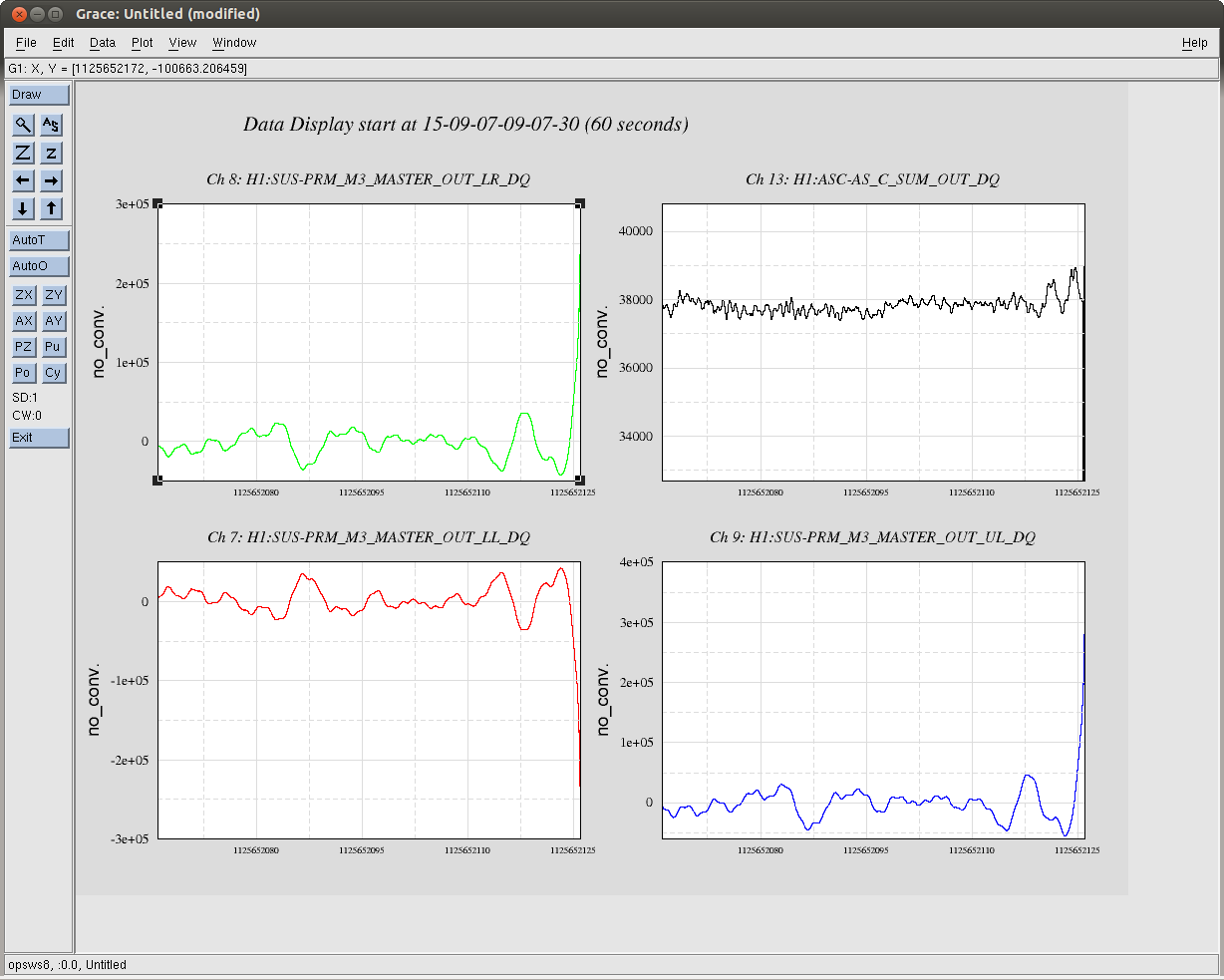
The SDF table has been updated with these new settings. We were all set to go back to science mode when the IFO lost lock, after 28 hours of good data. The lockloss was due to PRM M3 hitting the rails (see second plot), maybe because of a 6.4 earthquake, although the lockloss was about twenty minutes before the arrival time of the P-waves according to terramon.
What are the amplitudes of the dithers? Both in terms of mirror angle, and in BOSEM coil current (and then for both, the amplitudes relative to the beam divergence angle and to the max coil current).
The CW group is appreciative!
J. Kissel

To answer Peter's question, for an original amplitude of
       Freq    Amp
      [Hz]    [ct]
OM1   2125.1   150
      2150.1   120
OM3   2175.1   100
      2200.1   130
defined by the oscillator's clock gain in the OMC model, we propogatw it to the SUS model to the DRIVEALIGN matrix (which has ~10% off-diagonal elements), then through EULER2OSEM matrix, the DAC gain and the HAM-A coil driver + BOSEM coil transconductance, the current across the coil (assuming a 20/2^16 [V/ct], 16 bit DAC, and a HAM-A coil driver + BOSEM transconductance of 0.988 [mA/V] from T1200264):
Coil       UL          LL         UR          LR
          [mA]        [mA]       [mA]        [mA]
OM1      0.306       0.604      0.604       0.306
OM3      0.096       0.778      0.778       0.096
i.e. a coil current of at most ~0.8 [mA] at these frequencies,

And the displacement this causes on the HTTS (using 0.021 [N/A] from G1100968, a 0.048225 lever arm from D1001428, and the HTTS dynamical model at each frequency from using the httsopt_damp parameter set for the ssmake1MBf production single-stage suspension model):
                   P            Y
                 [rad]        [rad]
OM1   2125.1    3.37e-10    2.74e-10
      2150.1    3.21e-10    2.62e-10

OM3   2175.1    2.52e-10    2.01e-10
      2200.1    2.41e-10    1.92e-10
i.e. a displacement of roughly 3e-10 [rad] in both pitch and yaw at these frequencies.