peter.shawhan@LIGO.ORG - posted 21:42, Sunday 13 September 2015 - last comment - 06:38, Monday 14 September 2015(21484)
CAL-INJ_ODC bitmask misbehavior for ER8 hardware injections
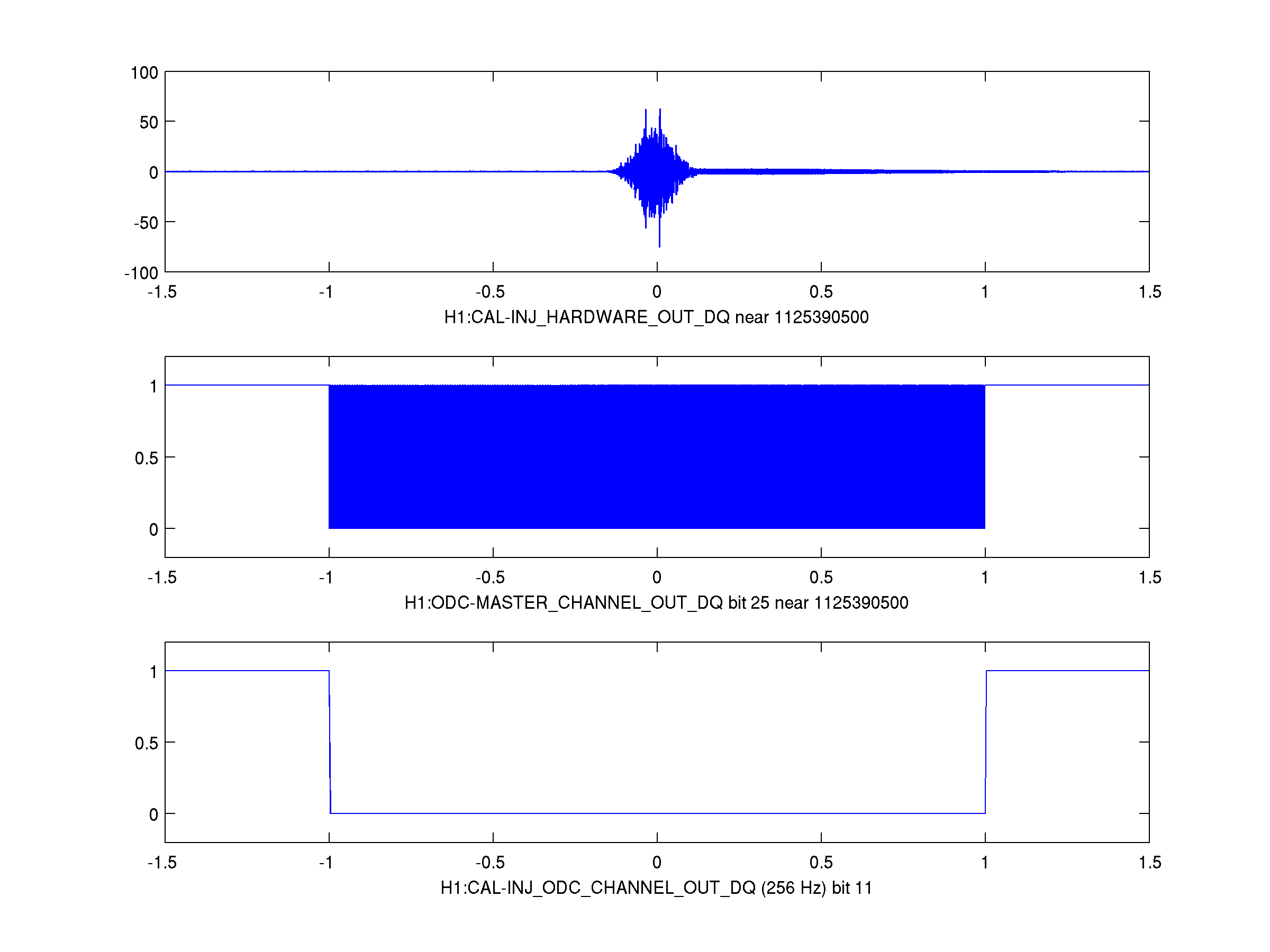
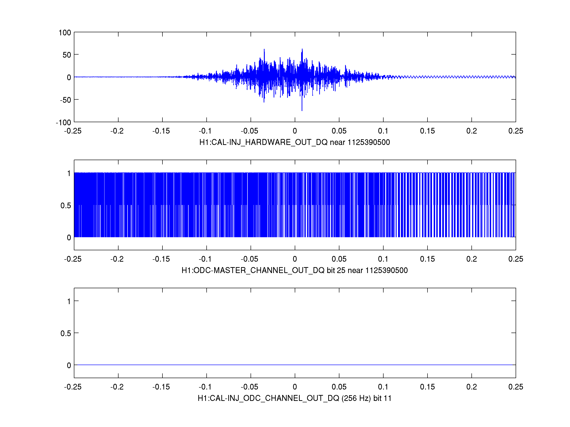
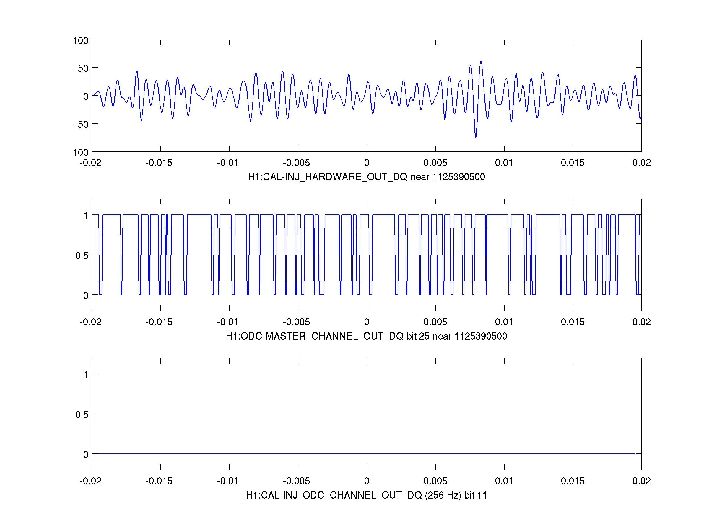
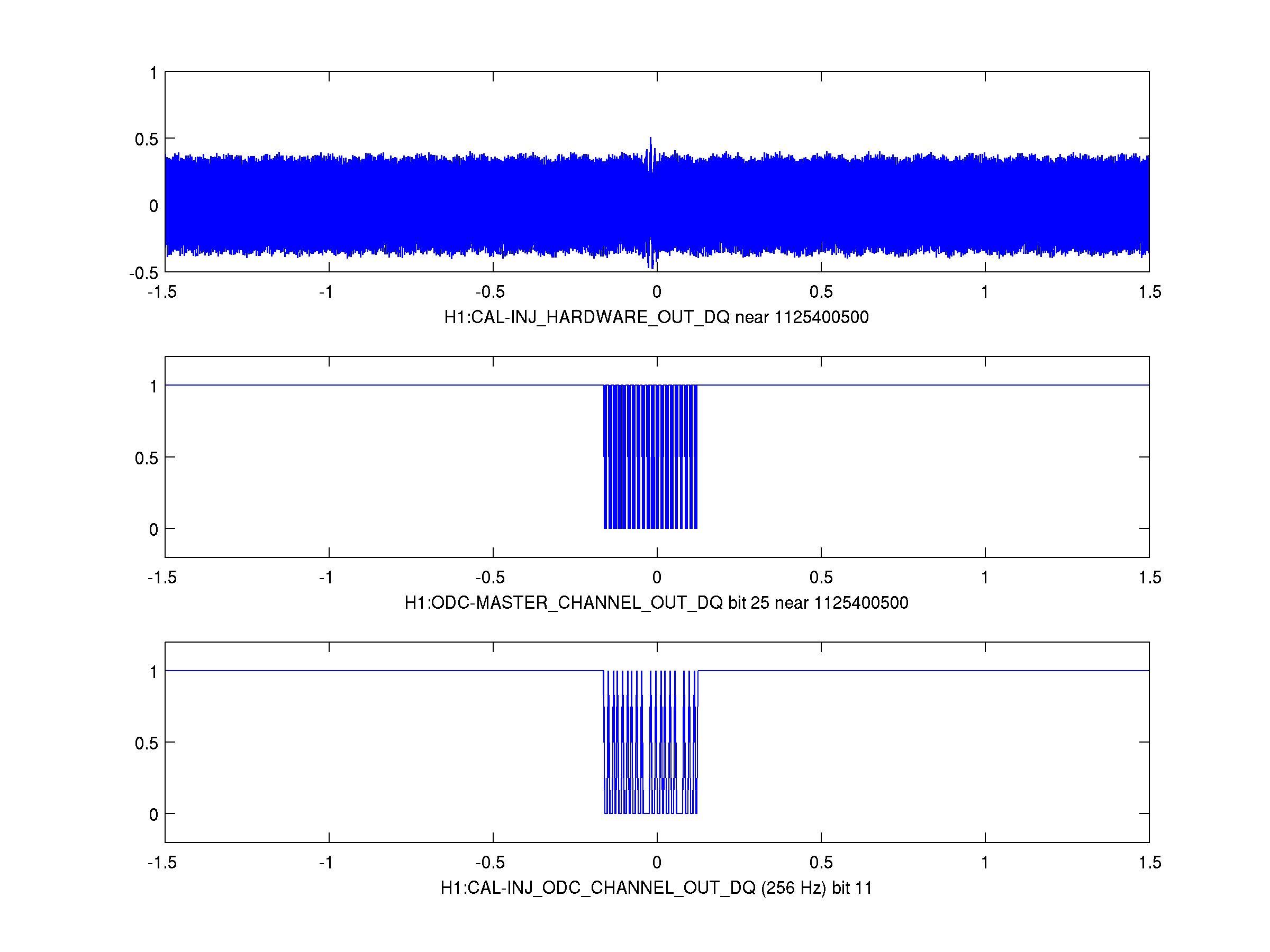
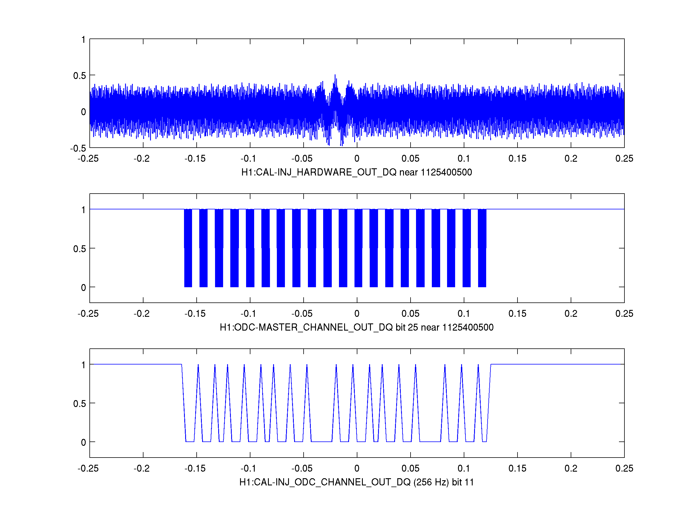
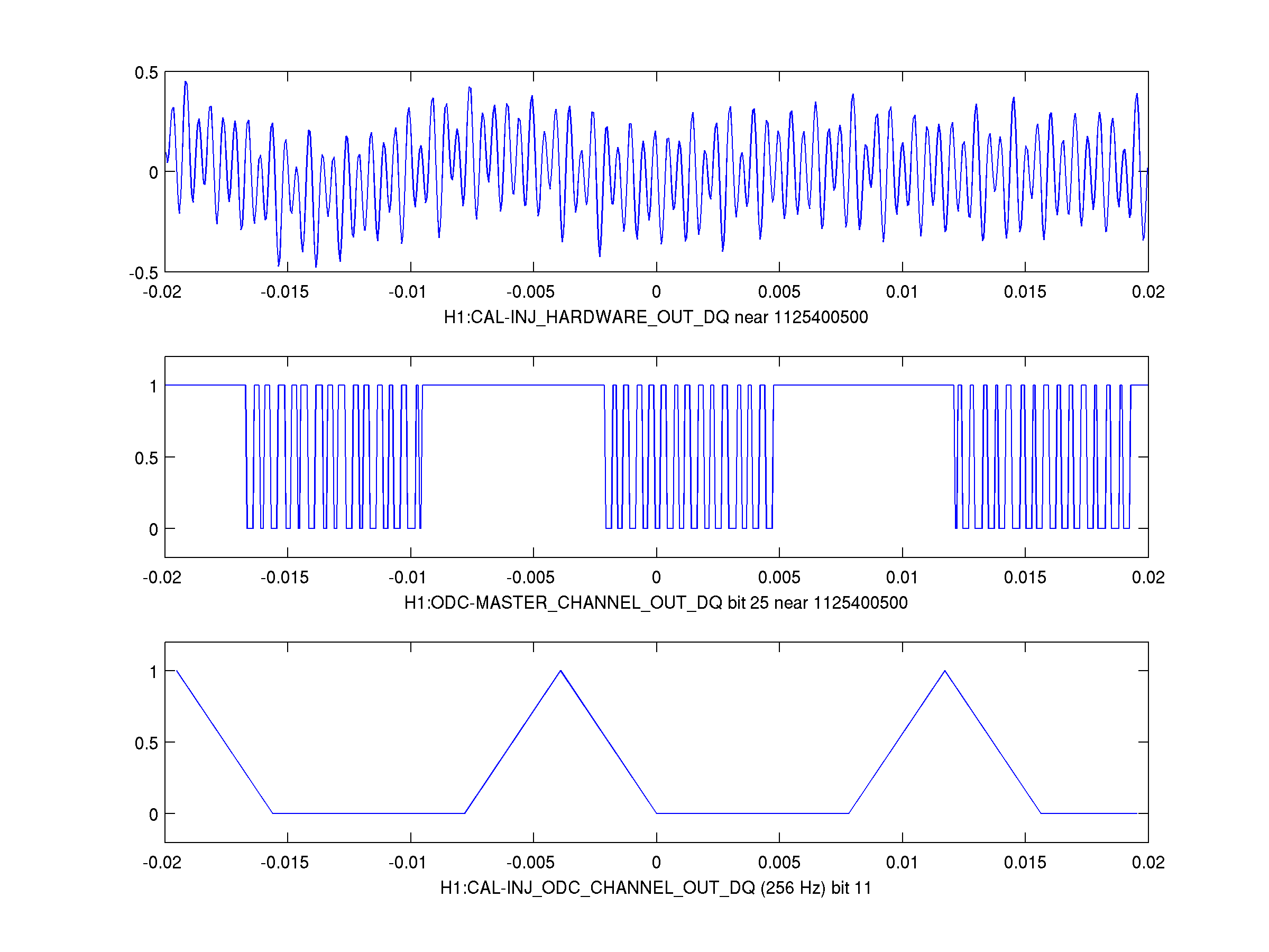
Cregg Yancey ran the hardware injection cross-checking code he has been developing, and noticed a curious discrepancy in the periods marked by the burst injection ODC bits at H1 versus L1 for the hardware injection at GPS 1125390500.  I investigated more closely, reading ODC bitmask time series from the recorded raw frame file along with the hardware injection excitation record, H1:CAL-INJ_HARDWARE_OUT_DQ.  I focused in on the bits which indicate burst hardware injections: bit 25 of H1:ODC-MASTER_CHANNEL_OUT_DQ (sampled at 16384 Hz) and bit 11 of H1:CAL-INJ_ODC_CHANNEL_OUT (sampled at 256 Hz).  What I found is rather startling: these ODC bits "flicker" between 0 and 1 around the time of the injection in a way that they definitely should not.  Each bit is supposed to equal 1 when there is no injection (meaning two or more consecutive samples with excitation amplitude less than 10^-200, according to LLO alog 18913) and 0 when there IS an injection.  The bit flickering pattern shows no obvious connection with the excitation time series.

The first three attached plots show what I found for the injection around GPS 1125390500, at three different time scales.  This is the "too-loud burst" injection which has been studied (see https://wiki.ligo.org/LSC/JRPComm/G181472) and seems to have been anomalous due to saturating the actuation chain.  However, the ODC bit setting should only be based on H1:CAL-INJ_HARDWARE_OUT_DQ, unrelated to saturation occurring anywhere later in the chain, so I believe this is a different problem.  Also, another injection at GPS 1125400500 seemed fine as an injected burst (it was a 69 Hz sine-gaussian) but still has the crazy ODC bit behavior, as shown in the last three plots.  There are even alternating "stripes" which are very odd.

Although I'm only showing plots here for H1, the problem occurs in a similar (though not identical) way in L1 data.  Therefore it is NOT restricted to one site.

Also, this bit problem did NOT occur for the ER7 injections; we checked the bitmask transitions and they all made sense.  It seems to have been introduced since then.  Perhaps the model code update described at LLO alog 18913 is not working as expected?
Images attached to this report
Comments related to this report
Isn't it nice when "sleeping on it" makes something more clear?  I woke up with a better understanding of what's going on -- I'm 90% sure this is the right story:

1. I was wrong when I wrote that the burst ODC bit is set based on CAL-INJ_HARDWARE (plotted as CAL-INJ_HARDWARE_OUT_DQ as I read it from the raw frame file).  Really it is set based on CAL-INJ_TRANSIENT (see, for instance, the CAL-INJ ODC documentation.  The CAL-INJ_HARDWARE channel is the sum of CAL_INJ_TRANSIENT and CAL_INJ_CW, so in the plots I made, much of the "fuzz" in the plotted trace is from the simulated pulsars in the CAL_INJ_CW channel; some of those are at high frequency, so the fuzz can have a fairly large amplitude.

2. There IS a bug in the way the ODC bit is set, but it is a deterministic, silly bug instead of something more devious.  When the code was updated to check for nonzero values using a threshold of 1e-200 instead of requiring them to be exactly zero to machine precision (https://alog.ligo-la.caltech.edu/aLOG/index.php?callRep=18913), I think they neglected to take the absolute value before comparing it to 1e-200.  (The expressions written in the CAL-INJ ODC document are consistent with that if taken at face value -- they do not have absolute-value lines.)  That MOSTLY explains the stripes seen in the 5th and 6th plots attached to the main alog entry here.  That injected signal was a 69-Hz sine-gaussian, and now I see that the period of the stripes is just about 1/(69 Hz).

3. The remaining question is why those stripes aren't solid blocks, i.e. why the bit value isn't just a square wave with a frequency of 69 Hz during the sine-gaussian.  I think the explanation for this is that the very small high-frequency component in the sine wave (or in the numerical discreteness noise in the way it was calculated or written out) was getting boosted by the inverse actuation filter SO MUCH that it is comparable in amplitude to the main sine-gaussian signal, so it can take the time series negative even when the SG waveform has swung positive.

So, I think the course of action is to confirm and fix the bug in the ODC code (missing absolute-values, probably for all comparisons with 10^-200).  In addition, the sky-high gain for high-frequency content in the injected signal is, I think, a problem, because there is always going to be SOME high-frequency content from finite machine precision even if the intended waveform is all at low frequency.  As the ER8 inverse actuation filters are developed and refined, I think it would be an excellent idea to roll off the gain above ~1 or 2 kHz to avoid problems.