jeffrey.kissel@LIGO.ORG - posted 00:21, Monday 14 September 2015 - last comment - 09:12, Monday 14 September 2015(21487)
Inverse Actuation Filter Installed; A Challenge -- and yet another reason to Switch to PCAL
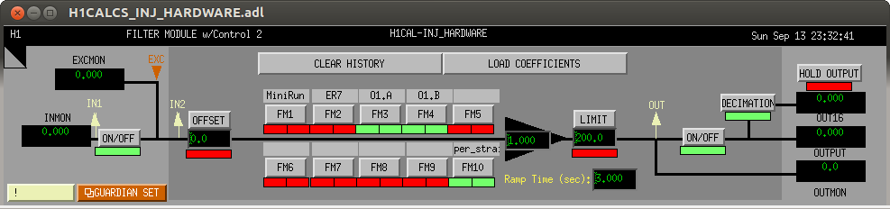
J. Kissel, M. Evans

After downloading the work that Matt has done (LHO aLOG 21424)carefully fitting the nasty actuation function we'd discovered (LHO aLOG 21419),
1) I've plotted it myself, to make sure I understand what Matt has given me
2) Inverted it, made sure I got the same residuals he did
3) Discovered the fit contained a pole at 15 [kHz], played around with the implications of moving the pole to the highest frequency foton accepts (8190 [Hz])
4) Painstakingly copied over to foton, because the fit poles and zeros did not all fit into one filter bank, and *I* wanted to control how they were divided between banks
5) Exported the foton filter, loaded it back into matlab, and fine tuned the necessary advance.

T'was a lot of work, but we have something installed and running. Now we beat the heck out of it to find the bugs, while we (in parallel) push injection through the photon calibrator forward.

In addition to this pain-in-the-tuckus inversion process, Joe Betz -- on the phone for other reasons -- brought up another excellent point: LHO does NOT use linearization on the H1SUSETMY electrostatic drive. While we get away with doing so during a quiescent lock, any loud control signal will expose the non-linearity (quadratic) nature of the ESD. We think we've already seen some evidence of this while measuring DARM open loop gain transfer functions. Yuck. PCAL has no such problems (in fact, though it uses an inherently quadratic AOM, it has analog electronics to ensure its linearity).

Note: Contrary to all of my suggestions, Matt *has* included and fit inverses to the notches in the actuation function. This means, while we will likely have the same amplification problems around the notch frequencies (see, e.g. LHO aLOG 20904), the phase reconstruction of all regions except this frequency is within 5 [deg]. Since there seemed to be competing interests in the CBC group on whether or not to include the inverse of the notches, I've left them in. If we need to remove them, and somehow retain the phase reconstruction in the surrounding frequency regain, then it'll be another day's worth of work between Matt and I. But honestly, if it comes to that, we're switching to PCAL.

%%
Details
%%
--------
Not much to say on the design here -- Matt did almost all of the work. The only two gotchas were as mentioned above: I had to move the highest fitted pole down and I must split the filter in to two parts. For the splitting, I chose to put everything from the (inverse) beam-splitter violin mode notch at ~300 [Hz] into the first module ("O1.A" in FM3), leaving the (inverse) QUAD violin notches and 950 [Hz] elliptic low-pass for the next ("O1.B" in FM4).

After exporting the product back into matlab, I tuned the timing advance to account for the pole that I'd moved down from the "ideal" fit.
Thus, all analysis should assume the waveforms need a timing advance of 255 [us].
Also, of course exactly surrounding the frequencies of the notches at ~300, 500, 1000, and 1500 [Hz] there is greater than 50% mismatch between the real SUS and the inverse actuation filter.

The first .pdf attachment shows
(pg 1) my reproduction of Matt's filter comparsion (over a little bit wider a frequency band),
(pg 2) the inverse function, both of Matt's ideal fit, and of the reconstruction from foton, and
(pg 3) a zoom in on the interesting region between 100 [Hz] and 2000 [Hz].

The second .pdf attachement shows a bode plot showing the breakdown of the filter between FM3 and FM4, and compares the filter against the ER7 filter.

Noteably, there is *not* a sign difference between the new filter and ER7 or the H1 Mini-run filter, but the phase has rotated once around the unit circle.  For a clear demonstration of this, see the third .pdf attachment. Recall, folks have been worried about the hardware injection filter since ER7 (see LHO aLOG 19948 for complete summary). I'm not sure how this ~360 [deg] rotation could be mistaken for a sign flip -- but maybe I'm just carrying around the term that was used during the initial guess of what the problem was, even though the real problem was more subtle. I've confirmed that neither the design string nor the "alternate" (i.e. as what foton interprets your design) show a minus sign in the gain.

--------
Configuration control:
(1) Stefan and I updated the ODC state vector for the hardware injections, since flipping the FMs from 2 to 3&4 make the "HARDWARE filter stated OK" light go red. To make green, we changed the recently modified bit status check from 0x1602 to 0x160c.
(2) I accepted the new filter bank state (and ODC bit word) into both the OBSERVE.snap and into the SAFE.snap for the CAL-CS front-end model.
I attach ascreenshot of the filter bank as I've left it.
Images attached to this report
Non-image files attached to this report

Comments related to this report
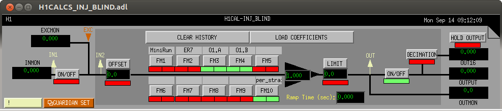
J. Kissel

The above inverse actuation filter has been copied into the blind injection filter bank, and is now on and running. The new configuration has been accepted into both the OBSERVE.snap and SAFE.snap files.
Images attached to this comment