Just in case you're wondering why LHO sees two noise bumps at 315 and 350Hz (attached, middle blue) but not at LLO, we don't fully understand either but here is the summary.
There are three things here, environmental noise level, PZT servo, and jitter coupling to DARM. Even though the former two explains a part of the LLO-LHO difference, they cannot explain all of it, and the coupling at LHO seems to be larger.
Reducing the PSL chiller flow will help but that's not a solution for the future.
Reimplementing PZT servo at LHO will help and this should be done. Squashing it all will be hard, though, as we are talking about the jitter between 300 and 370Hz and there's a resonance at 620Hz.
Reducing coupling is one area that was not well explored. Past attempts at LHO were on top of dubious IMC WFS quadrant gain imbalances.
1. Environmental difference
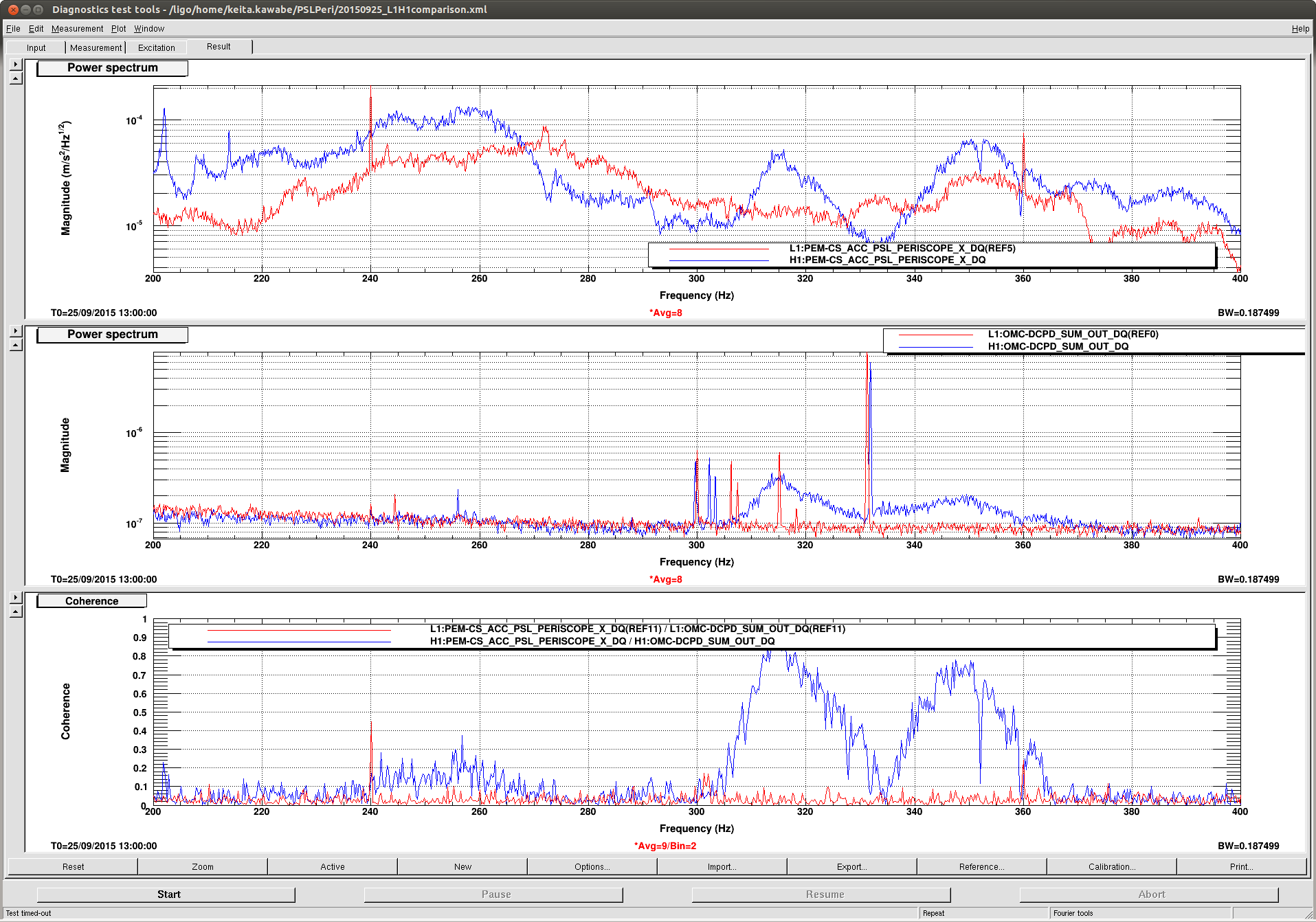
These bumps are supposed to be from the beam jitter caused by PSL periscope resonances (not from the PZT mirror resonances). In the attached you can see that the bumps in H1 (middle blue) correspond to the bumps in PSL periscope accelerometer (top blue). (Don't worry, we figured out which server we need to use for DTT to give us correct results.)
Because of the PSL chiller flow difference between LLO and LHO (LHO alog, couldn't find LLO alog but we have MattH's words), in general LLO periscope noise level is lower than LHO. However, the difference in the accelerometer signal is not enough to explain the difference in IFO.
For example, at 350Hz LHO PSL periscope is only a factor of 2 noisier than LLO. At 330Hz, LHO is quieter than LLO by more than a factor of 2. Yet we have a huge hump in DARM at LHO, it becomes larger and smaller in DARM but it never goes away, while LLO DARM is deat flat.
At LLO they do have a servo to supress noise at about 300Hz, but it shouldn't be doing much if any at 350Hz (see the next section).
So yes, it seems like environmental difference is one of the reasons why we have larger noise.
But the jitter to DARM coupling itself seems to be larger.
Turning down the chiller flow will help but that's not a solution for the future.
2. Servo difference
At LLO there's a servo to squash beam jitter in PIT at 300Hz. LHO used to have it but now it is disabled.
At LLO, IOOWFS_A_I_PIT signal is used to suppress PIT jitter targetting the 300Hz peak which was right on some mechanical resonance/notch structure in PZT PIT (which LHO also has), and the servo reduced the noise between about 270 and about 320Hz (LLO alog 19310).
Same servo was successfully copied to LHO with some modification, which also targeted 300Hz bump (except that YAW was more coherent than PIT and we used YAW signal), with somewhat less (but not much less) aggressive gain and bandwidth. At that time 300Hz bump was problematic together with 250Hz bump and 350Hz bump. Look at the plots from alog 20059 and 20093.
Somehow 250Hz and 300Hz subsided, and now LHO is suffering from 315Hz and 350Hz bumps (compare the attached with the above mentioned alog). Since we never had time to tune the servo filter to target either of the new bumps, and since turning the servo on without modification is going to make marginal improvement at 300Hz and will make 250Hz/350Hz somewhat worse due to gain peaking, it was disabled.
Reimplementing the servo to target 315 and 350Hz bumps will help. But it's not going to be easy to make this servo wide band enough to squash everything because of 620Hz resonance, which is probably something in the PZT mirror itself (look at the above mentioned alog 20059 for open loop transfer function of the current servo, for example). In principle we can go even wider band, but we'll need more than 2kHz sampling rate for that. We could stiffen the mount if 620Hz is indeed the mount.
3. Coupling difference
As I wrote in the environment difference, from the accelerometer data and IFO signal, it seems as if the coupling is larger at LHO.
There are many jitter coupling measurements at LHO but the best one to look at is this one. We should be able to make a direct comparison with LLO but I haven't looked.
Anyway, it is known that the coupling depends on IMC alignment and OMC alignment (and probably the IFO alignment).
At LHO, IMC WFS has offsets in PIT and YAW in an attempt to minimize the coupling. This is on top of dubious imbalances in IMC WFS quadrant gains at LHO (see alog 20065, the minimum quadrant gain is a factor of 16 larger smaller than the maximum). We should fix that before spending much time on studying the jitter coupling via alignment.
At LLO, there's no such imbalance and there's no such offset.
The coupling of these peaks into DARM appears to pass through a null near the beginning of each full-power lock stretch, perhaps indicating that this coupling can be suppressed through TCS heating.
Already from the summary pages one can see that at the beginning of each lock, these peaks are present in DARM, then they go away for about 20 minutes, and then they come back for the duration of the lock.
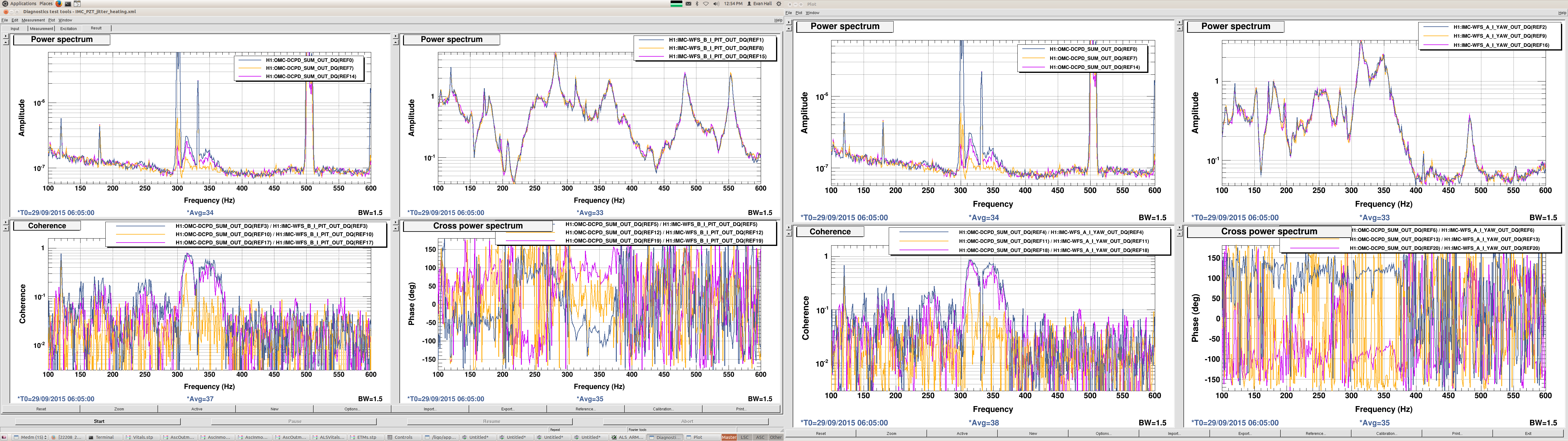
I looked at the coherence (both magnitude and phase) between DARM and the IMC WFS error signals at three different times during a lock stretch beginning on 2015-09-29 06:00:00 Z. Blue shows the signals 10 minutes before the sign flip, orange shows the signals near the null, and purple shows the signals 20 minutes after the sign flip.
One can also see that the peaks in the immediate vicinity of 300 Hz decay monotonically from the beginning of the lock strech onward; my guess is that these are generated by some interaction with the beamsplitter violin mode and have nothing to do with jitter.
Addendum:
alog 20051 shows the PZT to IMCWFS transfer function (without servo) for PIT and YAW. Easier to see which resonance is on which DOF.