The low-voltage electro-static driver (D1500016) includes monitors of the output quadrant drive signals that are sent to ADCs for sampling/monitoring (in a SUS IO chassis). The monitors look at the drive voltage after the normal inputs, test inputs, and parametric instability correction inputs are summed together. Each monitor path has a 1:4 voltage divider to fit the full driver range into the ADC input range.
Looking at these monitor channels for ETMY from a recent lock stretch shows several problems with these monitors as useful readbacks for the electro-static drive signals. In the attached plot, the two traces are:
- Red: analog monitor channel, in ADC counts (no scaling or filtering applied)
- Magenta: digital signal sent to DAC for ES-drive, scaled and filtered to show how it should appear at the analog monitor channel (filtering is 2 poles at 2.2 Hz, 1 pole at 42 Hz, 2 zeros at 50 Hz)
There are several problems:
- The sampling rate of the archived monitor channels is too low. It is set to 256 Hz, and the digital AA filter for that rate starts cutting off at about 85 Hz. The sampling rate should be raised to 2048 Hz.
- The monitor path in the driver chassis includes a low-pass filter at 42 Hz. This is just a mistake in the production of these chassis; the low-pass was intended to be at 1 kHz. This has been corrected by Rich for all the spare driver chassis.
- More significantly, the monitor channel shows excess noise above 8 Hz or so. Except for some higher amplitude features in the drive (like the calibration lines between 30-40 Hz), the monitor channels are swamped by this excess noise, and are incoherent with the DAC drive. Though not shown, I looked at a time when the interferometer was not locked, so that there was no signal going to the ES-driver: the monitor readback spectrum was at the ADC noise floor of 6e-3 counts/rtHz down to low frequencies (below 10 Hz), so with no signal, the excess noise is not present.
Followup work to do: i) check the behavior of the same channels on L1 for comparison; ii) test the behavior of the monitor channels with a spare unit on the bench, in the presence of a signal

It's analog. We need a usable whitening for this. (Daniel, Keita)
The noise floor is not a digital artefact, the analog gain seems to be too small to see anything useful at 100Hz. Even if we move 42Hz LPF up to 1k, we would still need a useful whitening, e.g. two stages of ISC style whitening.
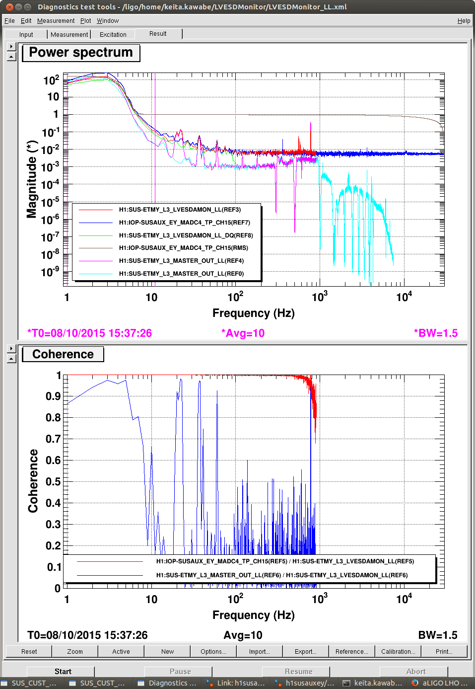
In the first attachment top, red, blue and green are the same ETMY LL ESD low voltage monitor at different points, i.e. red is the test point in SUSAUX (2k), blue is DQ of the same (256), and green is in the IOP model (64k) before the signal comes into SUSAUX.
Also shown is the digital output test point (pink and cyan, pink taken at the same time as red) projected onto the LV monitor by removing the whitening and putting 40Hz LPF and adjusting the DC scaling. No wonder we're not seeing anything useful at 100Hz.
RMS of IOP channel is basically 1 count down to 8Hz or so, and this means that the noise floor is just ADC noise. RMS of this same signal goes only up to 180 or so counts at 1Hz. Changing 42Hz LPF with 1k is not enough for frequency lower than maybe 400Hz or so.
Boosting the analog gain by a factor of 100 or so, the RMS at low frequency would become uncomfortably large.
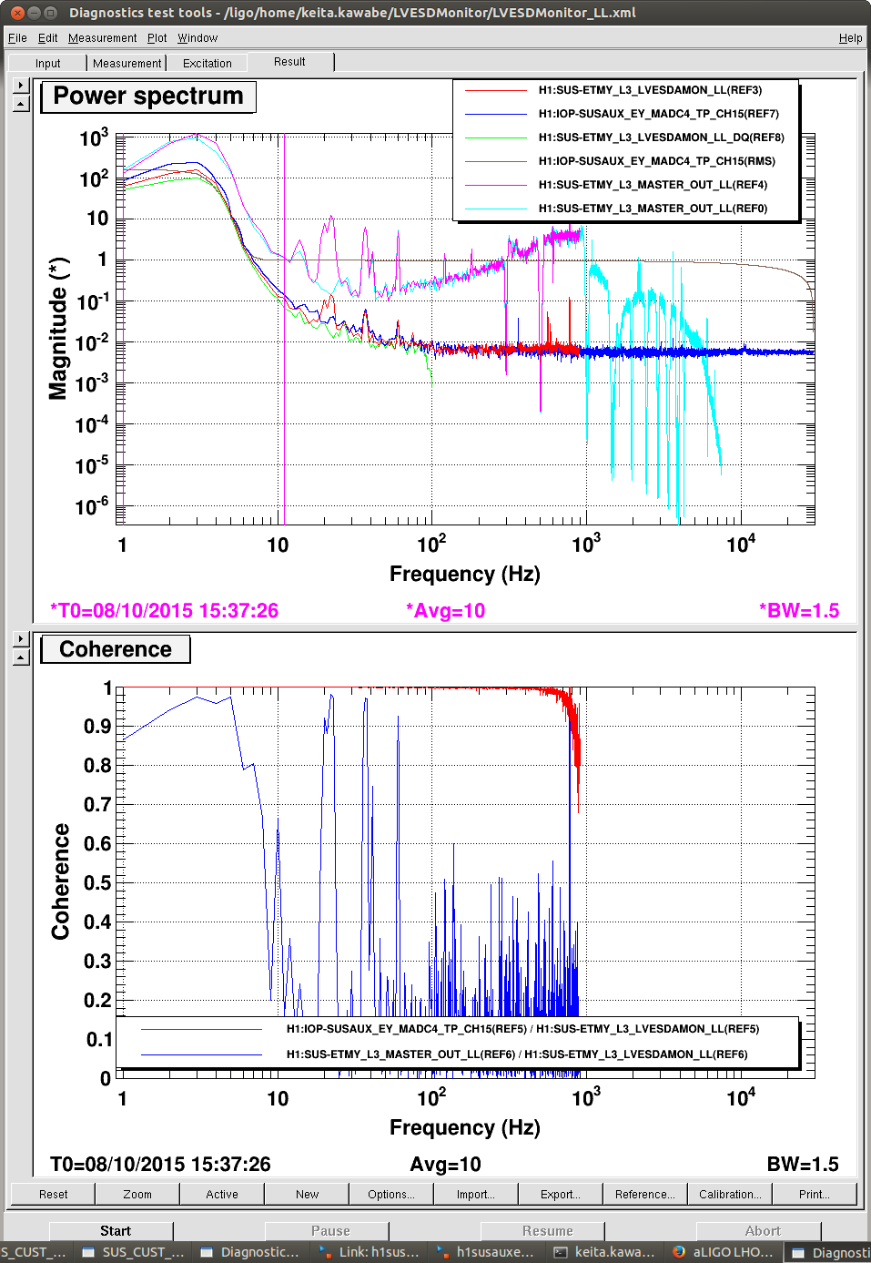
The second attachment shows what happens when there are two stages of ISC whitening (z=[1;1] p=[10;10]) plus 1kHz LPF instead of 42Hz, without changing DC gain.
The RMS between 1 and 10 Hz becomes 2000 counts-ish, RMS for f>10 becomes 100 counts-ish, and the monitor noise floor would be at least a factor of 10 larger than the noise floor for f<1k.
In the future, when our sensitivity increases by a factor of 3+ or something for f>100Hz and our drive drops by the safe factor, we might have to think about more whitening or more whitening gain. By that time, we might also be able to more aggressively cut down the low frequency part (f<5Hz) of the drive on ESD. According to Evan ESD-PUM crossover is about 20Hz (alog 19859) so it sounds doable.
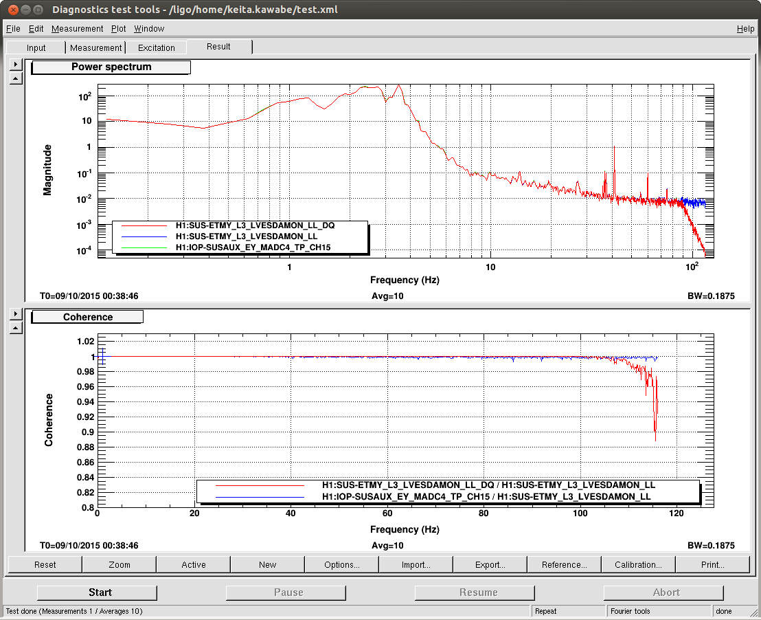
[update 0:40 UTC] The third attachment shows the DQ channel (red), test point (blue) and IOP channel (green, which is almost completely masked by blue) measured at the same time up to 116Hz. They're the same except decimation filters.