I have spent about an hour today checking some basic behavior of the ISS 2nd loop servo circuits. I did the following two measurements.
- Offset measurement
- Measurement of operating point as a function of the input power
No crazy thing was found in today's test. Our plan is that whenever we have issues with the ISS 2nd loop in some future, we will repeat the same type of measurements with an aim to identify what is changing.
Offset measurement
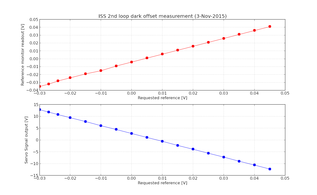
I checked how the reference signal propagates to the servo signal output by changing the reference signal. The measurement was done with the IMC intentionally unlocked. Therefore there was no light incident on the ISS PD array in HAM2. The result is shown in the first attachment. An important quantity to note here is the signal output value when zero reference voltage was requested. It was 2.76 V. Also note that zero output signal can be obtained when the reference signal is requested to be between 5 and 10 mV. This does not sound crazy to me. According to the resultant plot, the linearity seems also fine. Additionally I checked the reference monitor as well which also showed a good linearity. Later, I did a coarse version of the same test with the full power incident on IMC (~22 W). Even though the actual RIN was too high to make a precise measurement, the linear coefficient between the reference and output signals seemed consistent with what I have measurement with no light. I also attach the raw data in txt format.
Operating point measurement
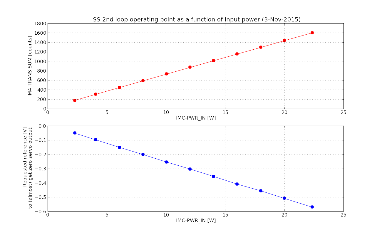
Then I locked the IMC and changed the input power step by step with a step size of about 2 [W]. In each step, I manually moved the reference signal such that the output signal stays around zero [V]. This tells us how the operating point evolves as a function of the input power. I did this test from 2 [W] to 22 [W]. The result is shown in the second attachment. As you can see in the plot, the operating point evolves linearly against the input power as expected. Additionally, I recorded IM4_TRANS_SUM as well in order to check the linearity of the output power of the IMC. IM4_TRANS seems to be also linear. The data in txt format is attached as well.
Note that all the tests were done with PD1-4 as an intensity sensor. PD5-8 was not checked during the tests.

There are two things that don't make sense.
1. DC gain mismatch between the drawing/traveller and the measurement.
When Second Loop boost, integrator and additional gain are all off and the variable gain slider is set to 0dB, the gain from REF signal monitor to Second Loop Output should be -220, taking into account the modification for the second loop electronics on the floor (D1300439, https://dcc.ligo.org/S1400214): -1 for the REF summation, -10dB (or 1/3.2) instead of 0dB for the variable gain amplifier, -100 for the last stage of "whitening" path (U34), and -7 for the daughter board.
D1300439 DC gain = -1/3.2*-100*-7=-220.
From Kiwamu's plots, the measured DC gain is about -12.5V/0.04V~ -310.
2. Mystery factor of two in REFSIG DAC output.
"REFSIG" slider has a mystery factor of 2 in the filter for the DAC output. As a result, when the slider is set to -0.577V, the output of the filter reads -1889 counts instead of -0.577V/40Vpp * 2^16ctspp = -945counts.
However, REF signal monitor, which I think is a read back of the offset voltage coming out of REFSIG DAC channel, reads -940 counts and 0.574V.