REMOVE SEARCH FILTER
SEARCH AGAIN
Search criteria
Section: H1
Task: SUS
Ibrahim, Betsy, Oli, Jason, Ryan C
Today, we finished with the FARO team (Ryan C and Jason) and confirmed that Pitch, Yaw, Vertical, Length (in-out) and Transverse (side-side) are all aligned within spec, which concludes the alignment of the BBS01 optic about the BBSS suspension - specific numbers in alog 90363
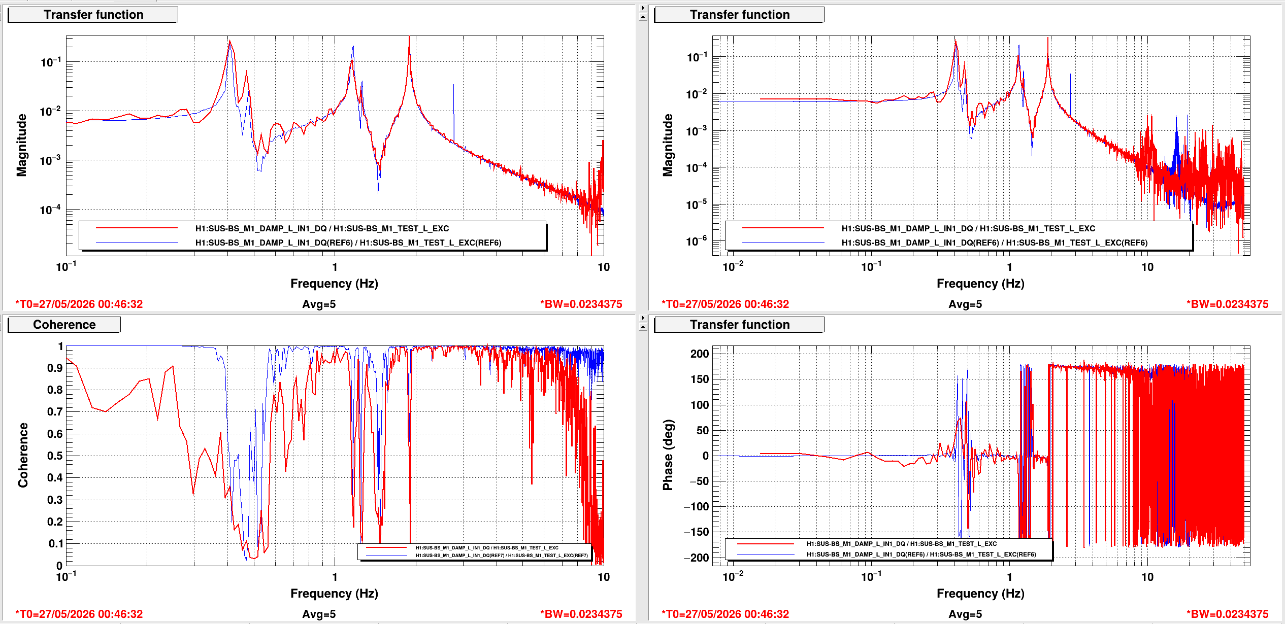
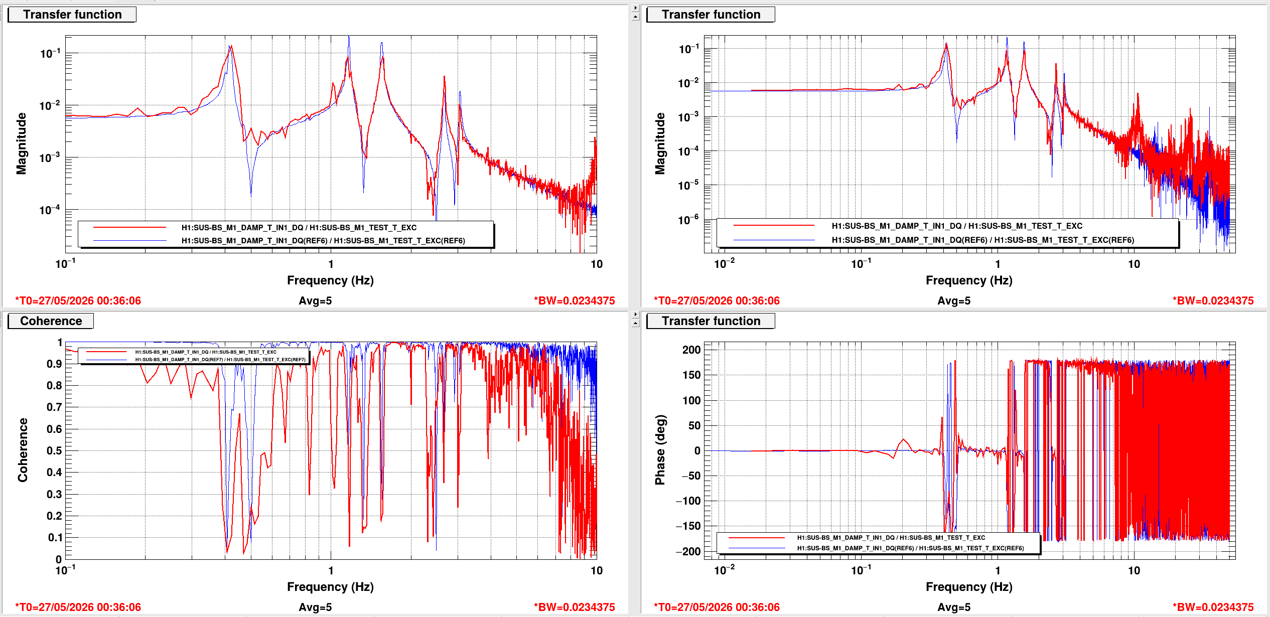
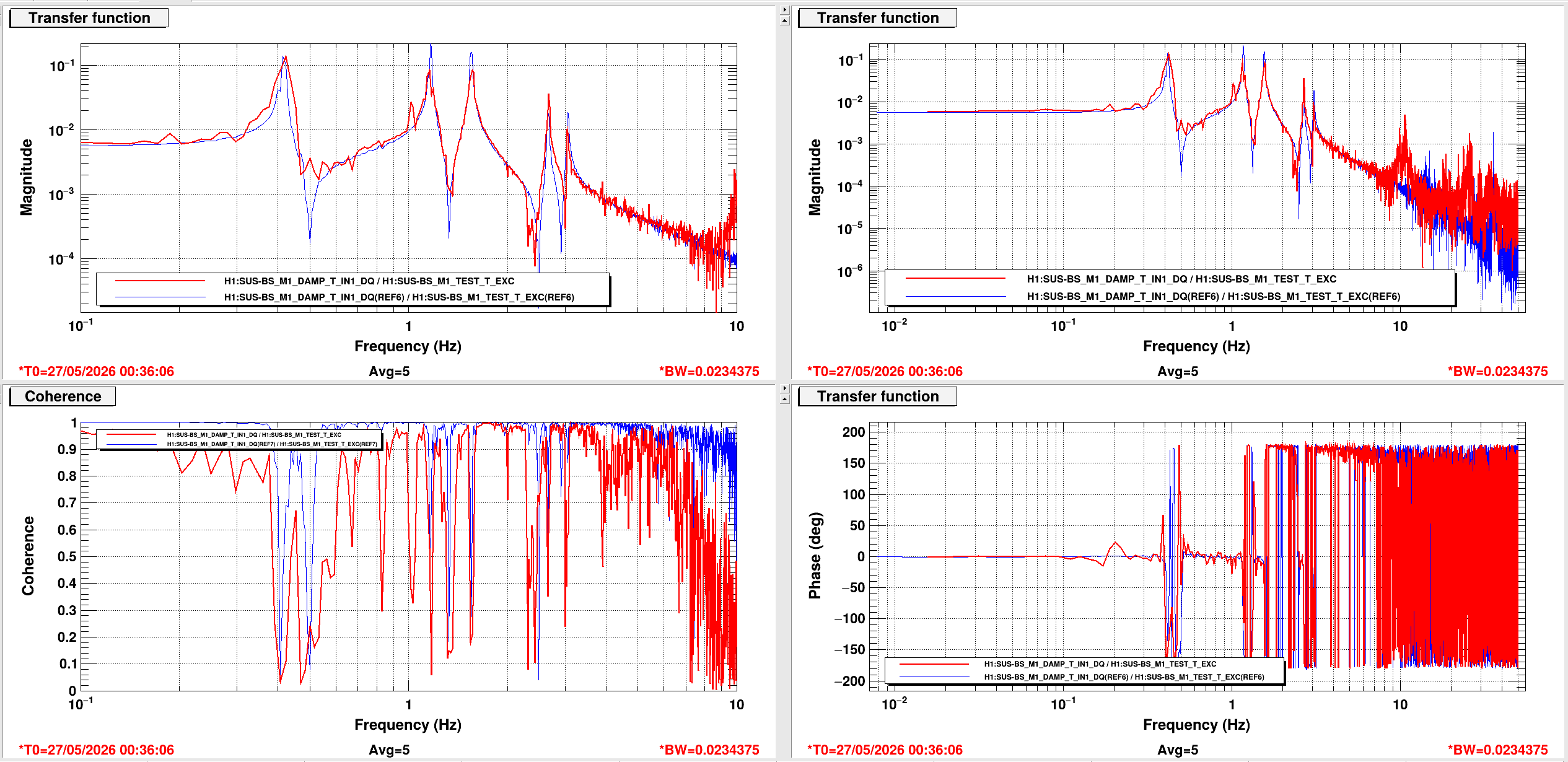
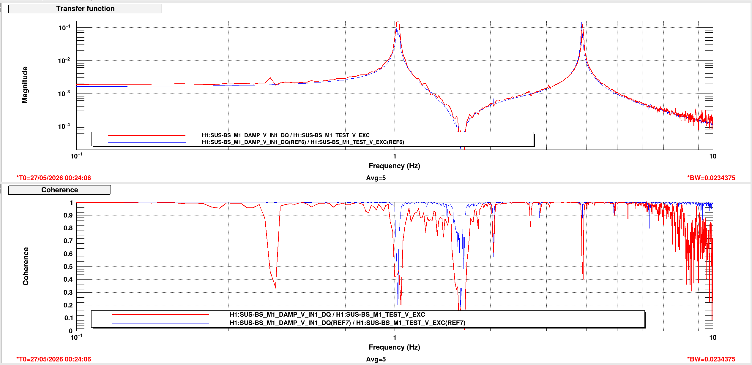
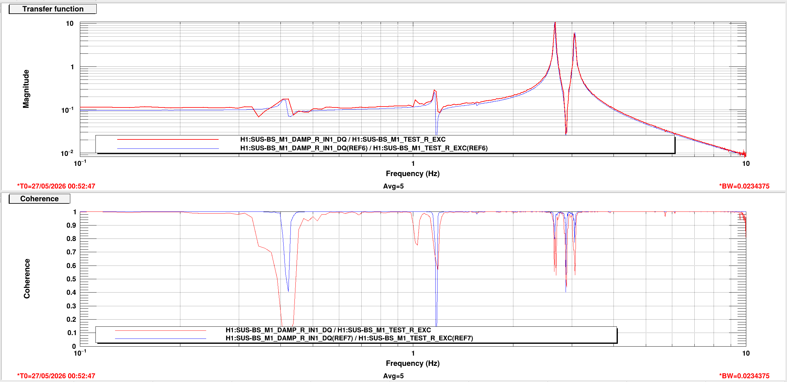
Transfer functions were taken throughout and can be found in alogs: 90356 , 90362.
Overall, the suspension dynamics with BOSEMs look good and now we're preparing for QOSEM install.
R. Crouch, J. Oberling, B. Weaver, I. Abouelfettouh
We have completed the BBS test stand alignment. After several rounds of yaw adjustment and figuring out the mechanics and what was rubbing where, we finally arrived at a yaw alignment within tolerance with everything torqued down and no rubbing in the SUS chain. In comparison, pitch alignment was a few twists on the adjustable mass in the PUM, maybe 20 minutes in total. The final pointing alignment deviations (yaw direction assuming a top-down view):
After the pointing alignment was complete we then moved back to the AR side to check that the position had not changed. The BBS cage has not been moved on the ISI, so our alignment of the cage reported here is still valid. The results (tolerance for all is +/- 1.0 mm):
Rotating from our IAS equipment basis to the IFO axes, shifting the deviations from the AR to the HR surface, and adding the pointing alignment, the final test stand position of the BBS HR surface is shown in the below table (CW = clockwise; CCW = counterclockwise; reported assuming a top-down view):
| Target | Actual | Deviation | Tolerance | |
| X | -202.6 mm | -202.3 mm | +0.3 mm | +/-1.4 mm |
| Y | -184.1 mm | -183.8 mm | +0.3 mm | +/-1.4 mm |
| Z | -83.1 mm | -83.2 mm | -0.1 mm | +/-1.0 mm |
| Pitch | -446 µrad (up) | -431 µrad (up) | +15 µrad (down) | +/-55 µrad |
| Yaw (from -X axis) | -785.918 mrad (CW) | -785.758 mrad (CW) | +160 µrad (CCW) | +/-190 µrad |
I've kept the yaw angles in radians for consistency, but converting them to degrees gives a target yaw from the -X axis of 45.0298° CW and an actual yaw of 45.0206° CW, with a deviation of 0.0092° CCW.
We've left the IAS equipment in the West Bay near the test stand in case we need to take a look at alignment again, but as of now the test stand alignment is complete.
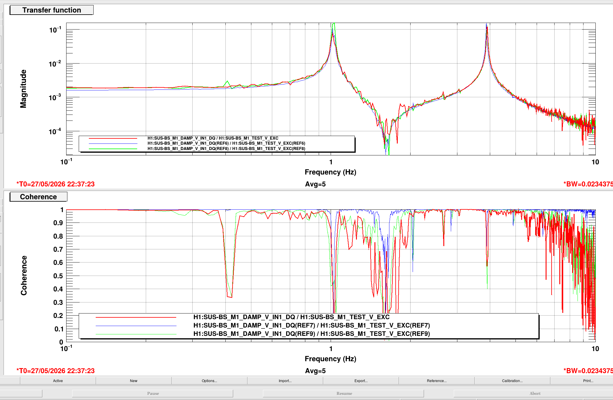
Took a couple transfer functions for T, V, and P to just check on the OSEMs. All three dofs, so all osems, are looking good.
The measurements can be found in /ligo/svncommon/SusSVN/sus/trunk/BBSS/H1/BS/SAGM1/Data/2026-05-27_2200_tfs/2026-05-27_2200_H1SUSBS_M1_WhiteNoise_{T,V,P}_0p02to50Hz.xml and are committed as r13022.


After figuring out the damping issues for the BBSS yesterday (90341), we took some transfer functions to check for rubbing or anything else weird after all the alignment work that has been occurring.
These measurements were taken using BOSEMs, and have the correct DAC compensation value of gain(4096) in the COILOUTF filter bank.
Data
/ligo/svncommon/SusSVN/sus/trunk/BBSS/H1/BS/SAGM1/Data/2026-05-26_1700_tfs/2026-05-26_1700_H1SUSBS_M1_WhiteNoise_{L,T,V,R,P,Y}_0p02to50Hz.xml
r13020
Results
/ligo/svncommon/SusSVN/sus/trunk/BBSS/H1/BS/SAGM1/Results/2026-05-26_1700_tfs/2026-05-26_1700_H1SUSBS_M1_ALL_TFs.pdf
r13021


J. Kissel, O. Patane, B. Weaver, I. Abouelfettouh

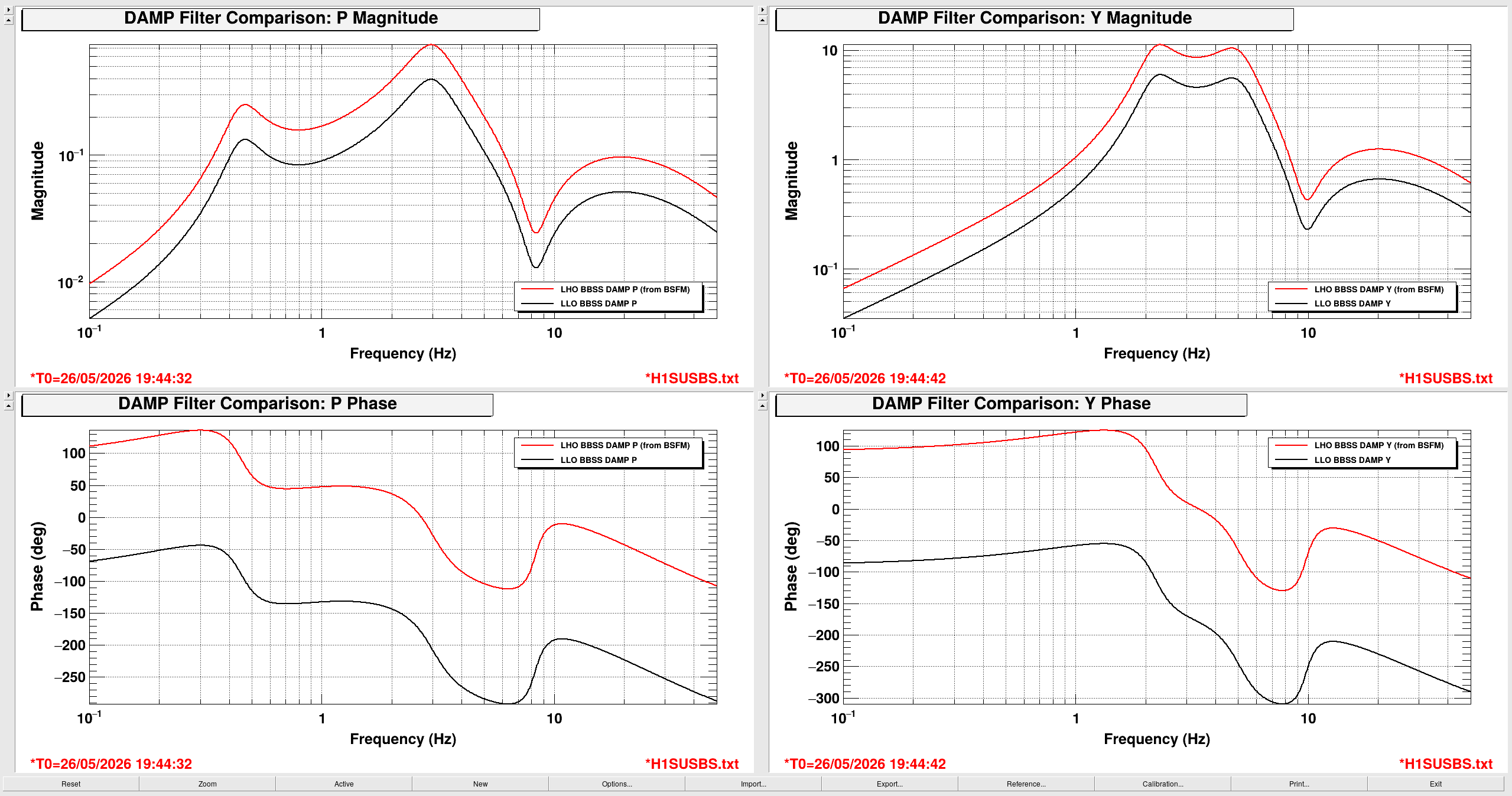
Executive Summary: For now, we can damp the BBSS Glass BS with BOSEMs and old Level 2 BSFM Glass BS damping loops as long as the L and P EPICs gains are -0.5, all other DOFs are -1.0, and we turn OFF all DOFs of the BSFM bounce/roll mode notches.

Debugging damping loops for BBSS with BOSEMs mounted to the table cloth, we found that with direct copy of "old" level 2 damping loops for BS (a BSFM) was unstable, ringing up in L and P at 2.668 Hz (measured with t-cursors on an ndscope session).

This is not a huge surprise; we'd already modeled the phase margin with this direct copy SWG:12301 has very low phase margin (modeled to be 23.8 [deg], with the highest upper unity gain frequency crossing at ~2.5 Hz; see dampingfilters_BBSS_2025-07-09.pdf page 33). Plus, experience has taught us that measured TFs often have more phase loss than models, so the phase margin of the loops is likely even less -- hence instability from 1/(1+G) gain peaking.

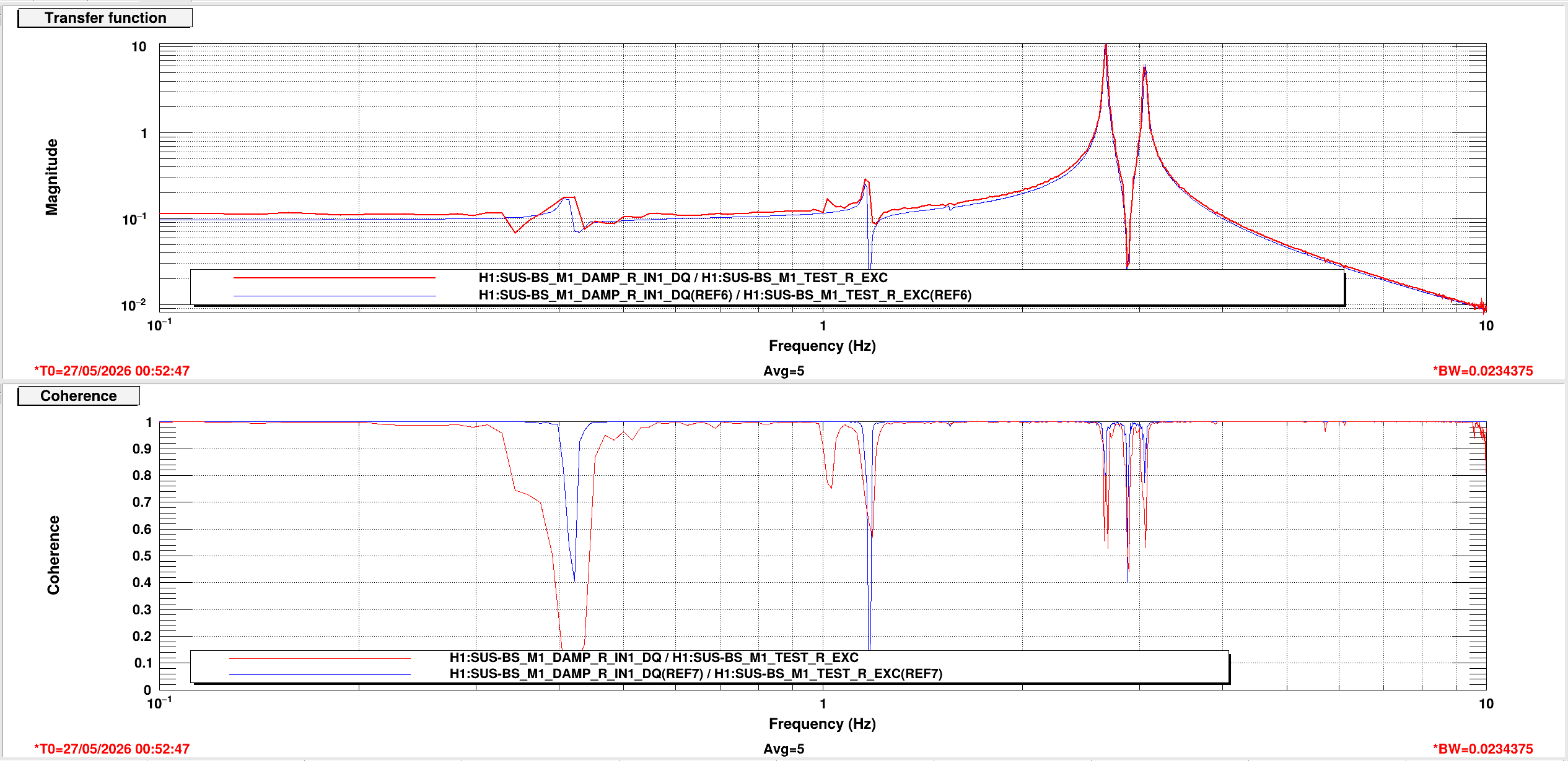
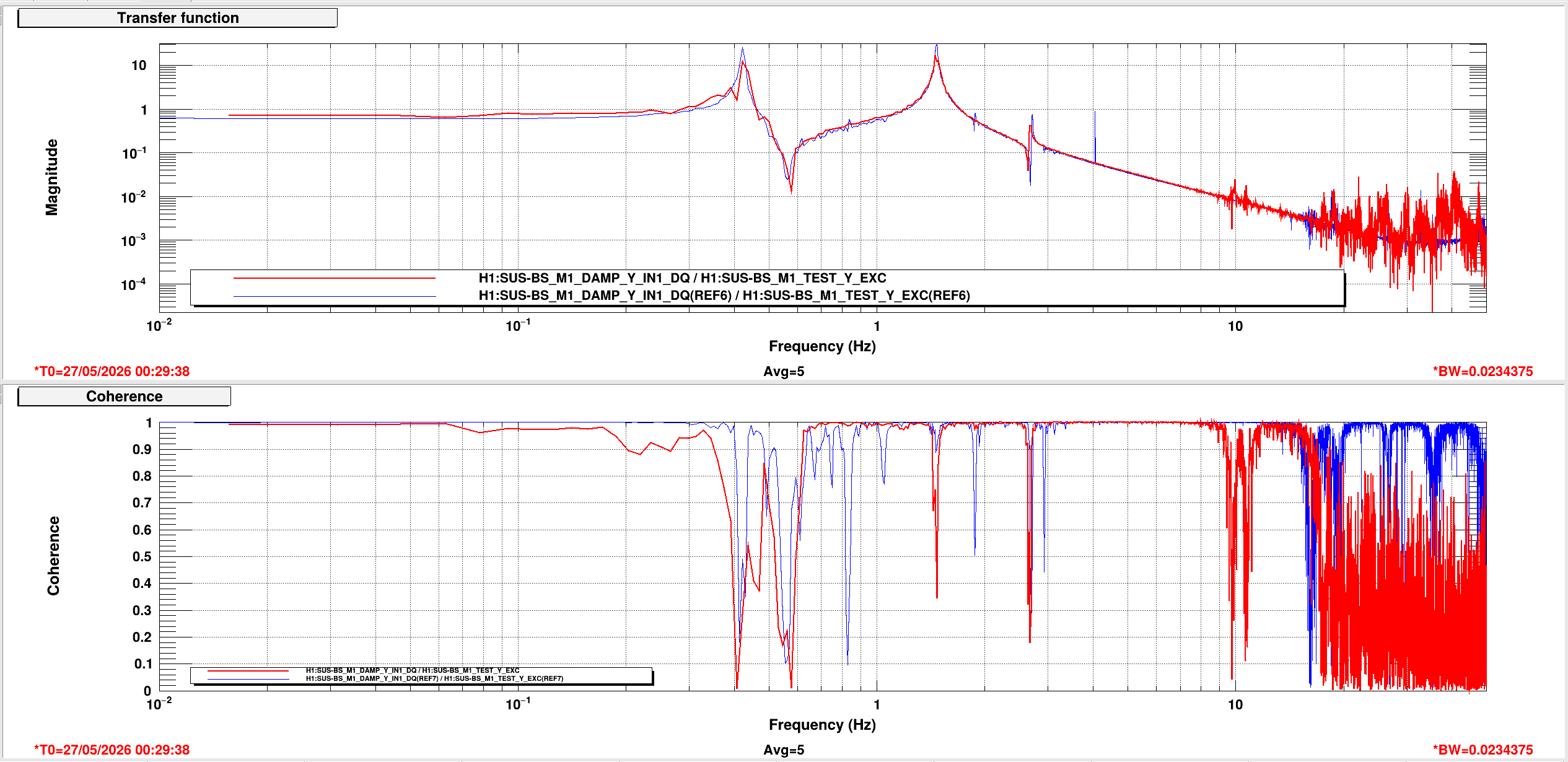
Ibrahim took some preliminary undamped TFs to confirm the (undamped) dynamical TFs of the BBSS with a glass optic. With what poor coherence we have in air, we can at least eye-ball confirm that they're not substantially different from the metal build on the test stand. Good! Great! We'll try to get these TFs better and Ibrahim will post for reference.

OK, with the dynamics checked out, on to the damping loops. Thus far the team had just rammed all the Level 2 BSFM loops on with a gain of -1.0, as we'd run them for years with the BSFM BS.

So, we did the dumb things first:
    - We turned OFF the BSFM's BS highest bounce ("SB17.79" FM8) and roll ("SB26.06" FM9) mode frequency notch filters. We know these are the wrong frequency, and they're just eating up phase. (We plotted them, and it's not much at ~2 Hz, but they're the wrong frequency for a BBSS, so we just turned them OFF.)
    - Turned on DOFs one or two at a time to narrow down which DOF(s) are problematic. T, V, R, and Y close fine and are stable with the old BSFM filters with a gain of -1.0. L and P are the loops that buzz at the 2.625 Hz (0.005 Hz resolution ASD with DTT).
    - Just reduce the overall gain of the loop(s) -- tried P at -0.5 and -0.25 with L still at -1.0. That was still unstable. But, L, P = -0.5, -0.5, is nicely stable, and damps stuff.

Getting slightly smarter, we checked in with the hard work of Vlad from LHO:81178 and found that the L and P filters have an EPICs gain of -1.0, and are identical in frequency response -- but the *filter* overall gain is a factor of 1.88x lower (i.e. essentially a factor of 2.0x). So -- he had to do essentially the same thing we did (though if I know Vlad, he actually measured this factor of 1.88x rather than blind guess like we did). Note that LLO's already using QOSEMs.

So, for now, we have something stable. Over time, we'll work on improving it, but this'll do. Once we have time, we'll take open loop gains, see exactly where we need phase, and adjust. Smart: Shouldn't need that much, change honestly.
Just as I said in the acceptance review; Slides 33 and 34 of E2500057, we can easily relax the P low-pass filter and then regain the on-resonance pitch damping that we lost from dropping the overall gain by 2.0x.
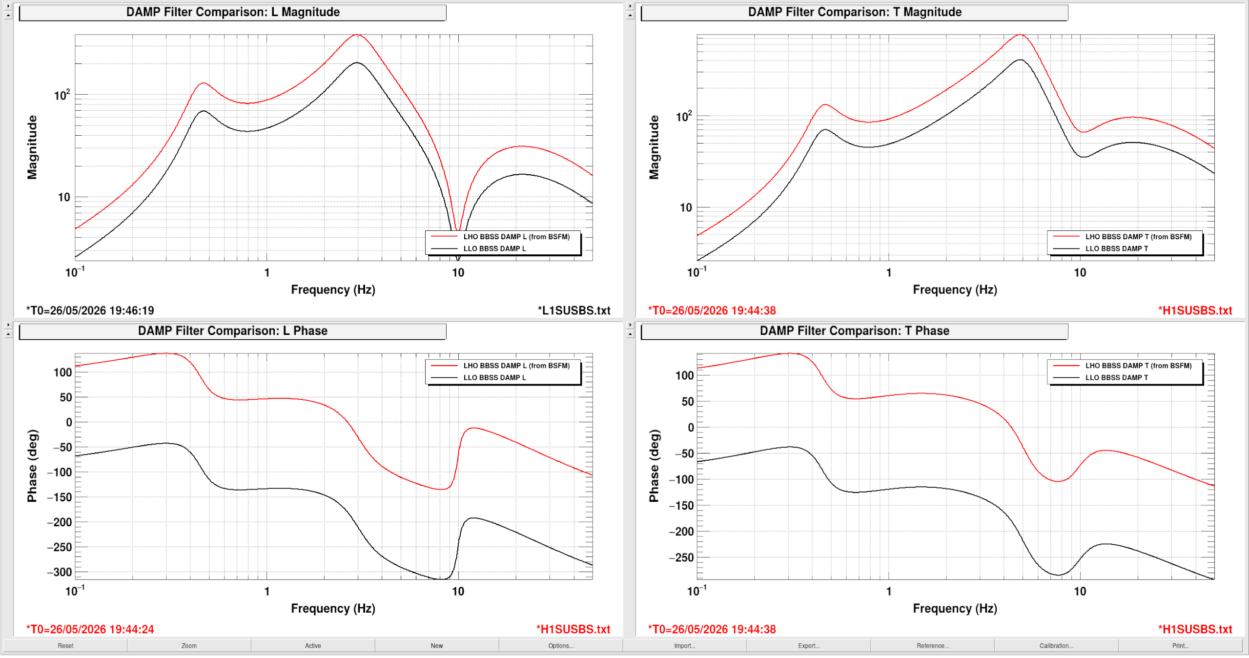
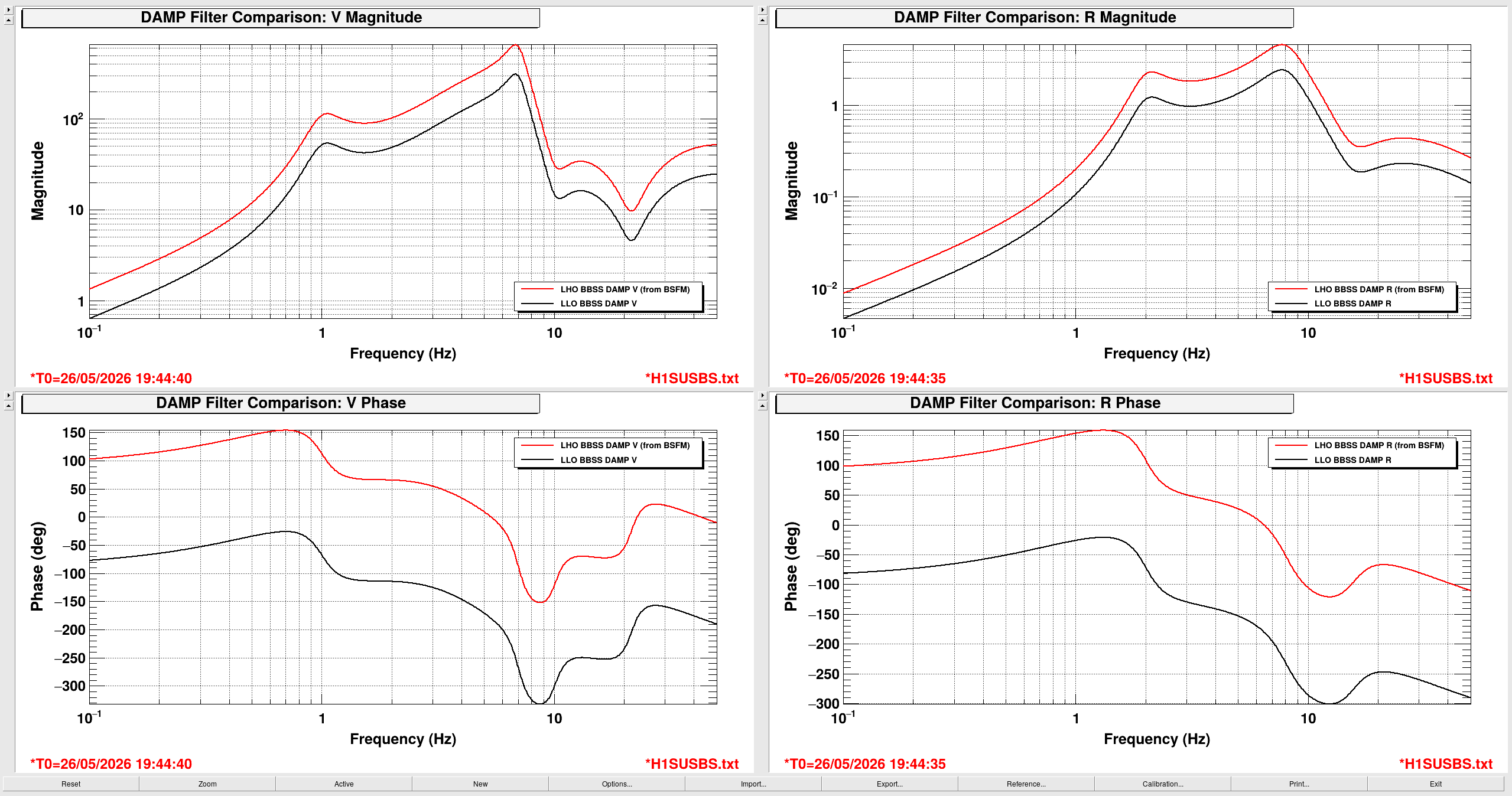
Adding in comparison plots between LLO an LHO's current beamsplitter damping configurations. Like Jeff said, LLO's damping loops have a factor of 1.8 less gain than ours, and that's true for all degrees of freedom (L&T, V&R, P&Y).
I also took a closer look at each site's filters for subtle differences between the sites (table), and it looks like the main difference is gains, which makes sense considering what we can tell right away from looking at the plots.
Another quick note: currently on the test stand, the normal breathing frequencies of the BBSS seem to be:
L, T, R, P, Y: 0.4 Hz
V: 1.05 Hz
Transfer functions taken after this debugging are in 90356

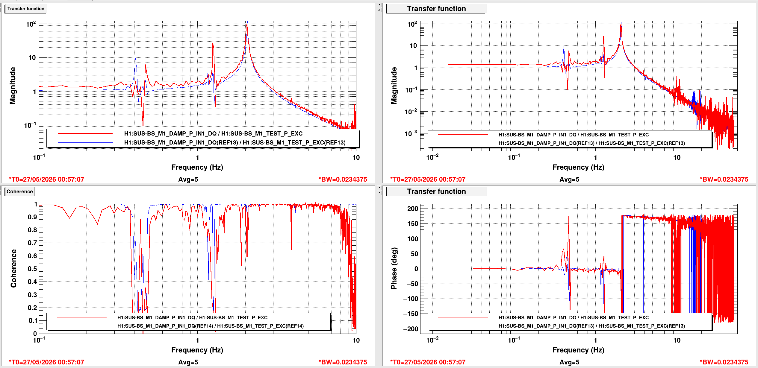
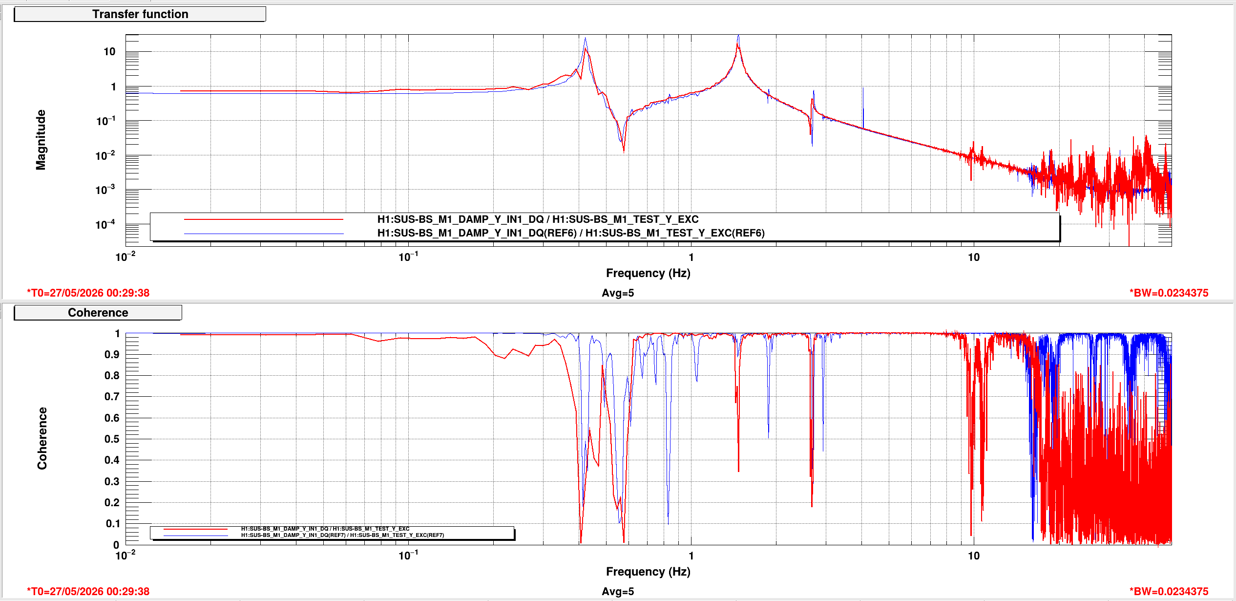
(Betsy, RyanC, Jason)
Friday we spent more time understanding why the Yaw mechanics weren't effective on the BBSS. We found that a lot of the top mass OSEMs interfere a lot when adjustments are made so they were constantly hanging up and giving us false reading of our adjustments. So we ended up disassembling half the suspension, stripping all top BOSEMs and the middle stage 4-BOSEMs via the entire plate. Then we started to see actual Yawing with the adjustments. In the process however, we stripped one of the 10 blade locking screws. So more disassembly to remove the sheet plate and eventually the bolt. We now have yaw in the ballpark, but need damping. Facepalm. So will resume reassembling the whole suspension and get damping going asap next week. Will need to revisit the L measurement after we finish Y and P.
On May 19th, 2026, we took our first set of transfer functions for the BBSS after swapping in the glass optic. They all came out looking good, albiet very noisy because the suspension wasn't covered.
Comparing them to the last measurement we did in the staging building, the peaks still all match up well. There is just a consistance difference in magnitude, but that is probably just due to the difference in electronics between the QUAD stand in the staging building and the BS electronics in the LVEA.
Data
/ligo/svncommon/SusSVN/sus/trunk/BBSS/H1/BS/SAGM1/Data/2026-05-19_2000_tfs/2026-05-19_2000_H1SUSBS_M1_WhiteNoise_{L,T,V,R,P,Y}_0p02to50Hz.xml
r13018
Results
/ligo/svncommon/SusSVN/sus/trunk/BBSS/H1/BS/SAGM1/Results/2026-05-19_2000_tfs/2026-05-19_2000_H1SUSBS_M1_ALL_TFs.pdf
r13018
/ligo/svncommon/SusSVN/sus/trunk/BBSS/Common/Results/allbbss_May2026_BBSS_teststand_vs_staging/allbbsss_May2026_BBSS_teststand_vs_staging_ALL_TFs.pdf
/ligo/svncommon/SusSVN/sus/trunk/BBSS/Common/Results/allbbss_May2026_BBSS_teststand_vs_staging/allbbsss_May2026_BBSS_teststand_vs_staging_ALL_ZOOMED_TFs.pdf
r13017

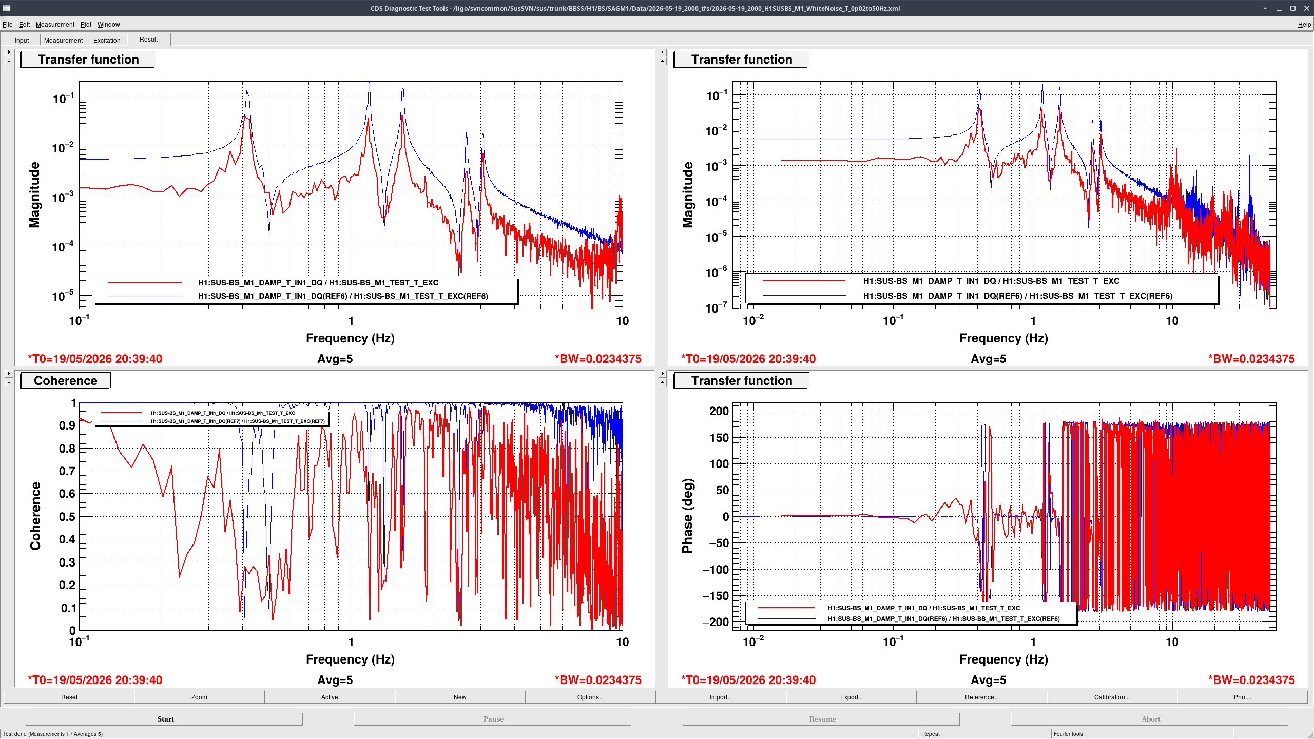
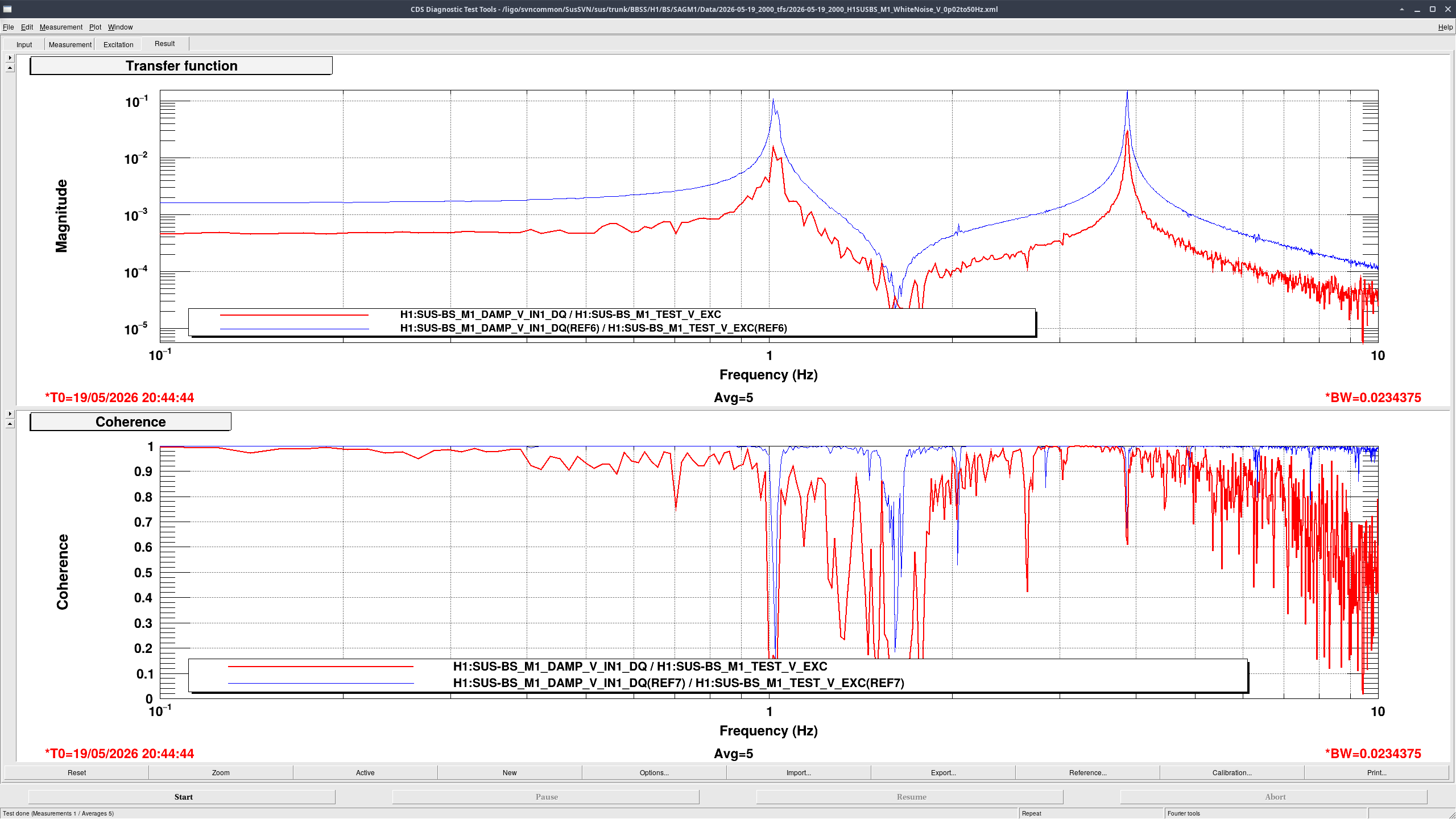
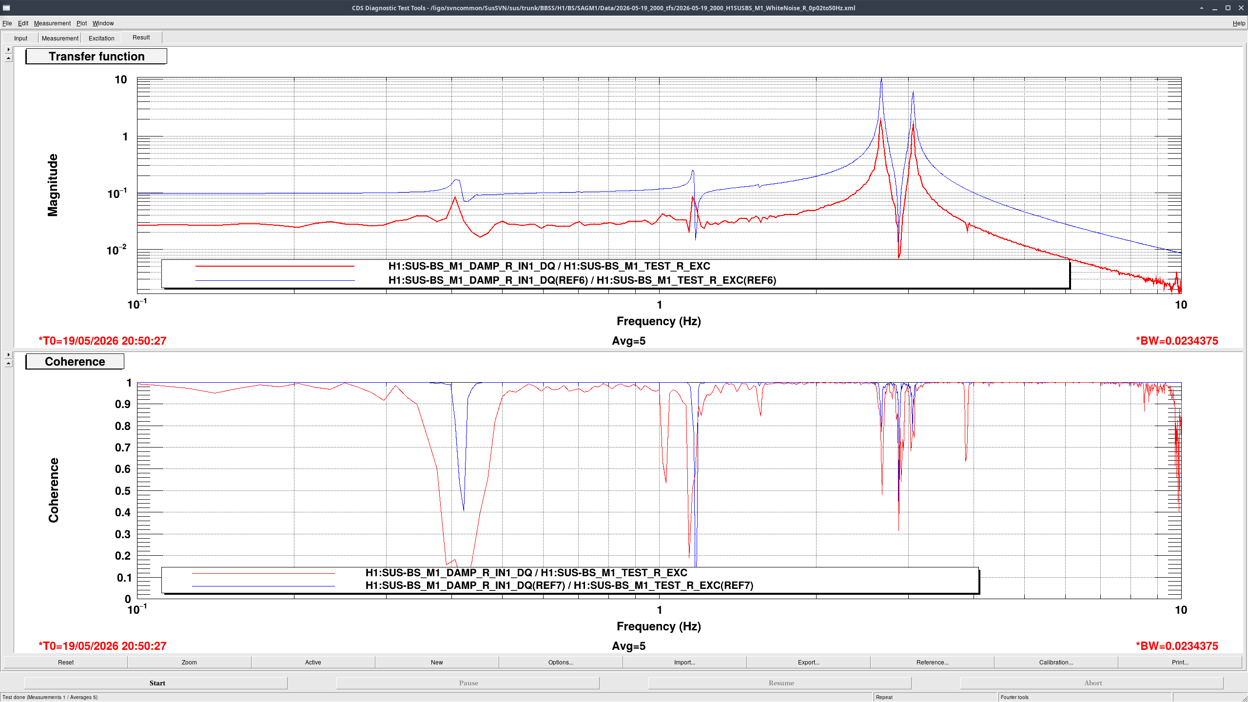
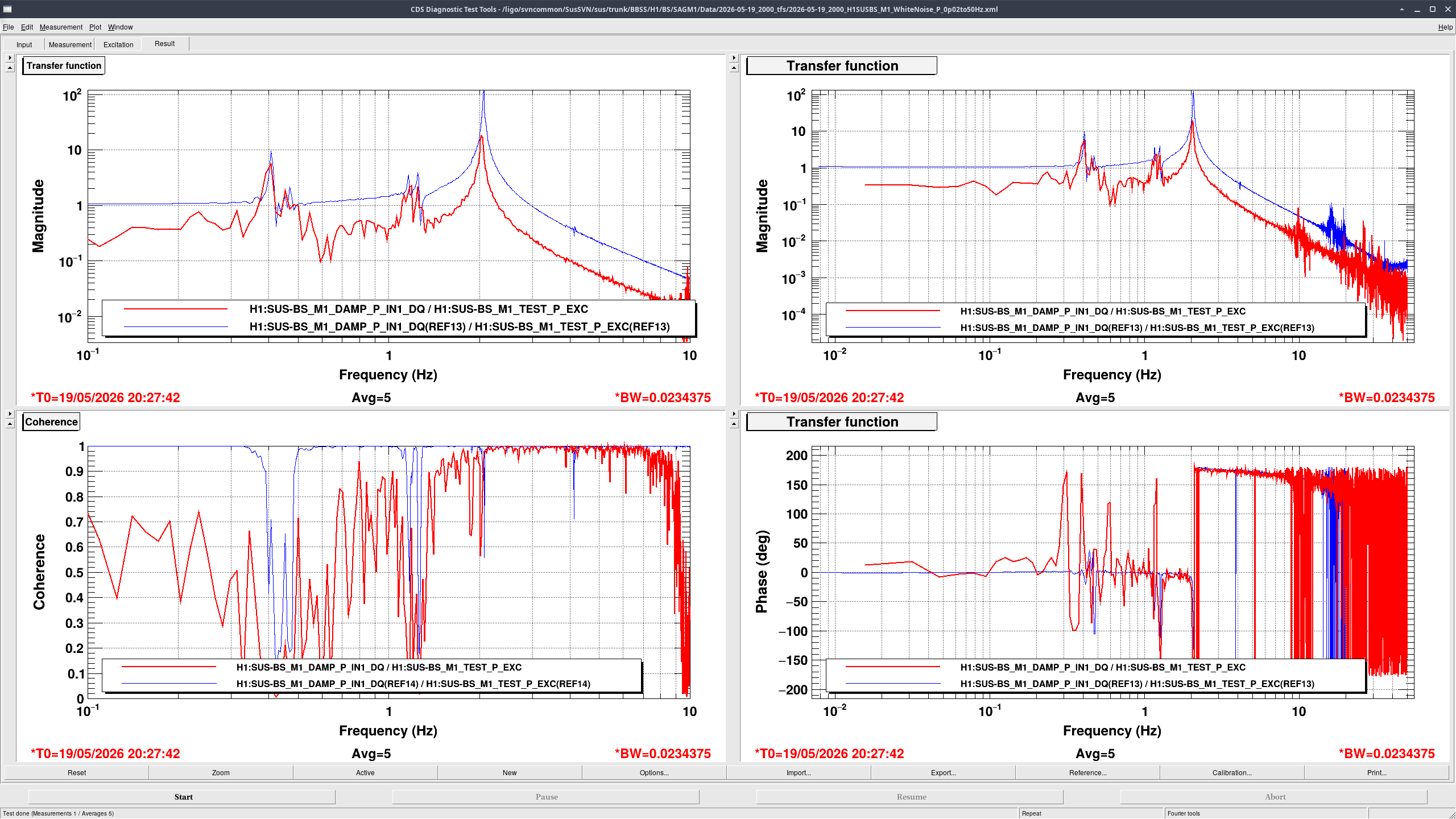

These measurements were taken with BOSEMs. The extra factor of ~4 that these measurements are lower by as compared to the older staging building trace is due to electronics. The BSFM was moved from 18- to 28-bit DACs back in January, so I compensated for this change in the COILOUTF filter bank by adding a filter module with a gain of 1024. However, the BBSS measurements made in the staging building were using a 16-bit DAC, so when we moved the BBSS onto the BSFM system, there was a factor of four of drive missing from excitations, hence these measurements looking lower as compared to the measurements in the staging building. That was remedied after this.
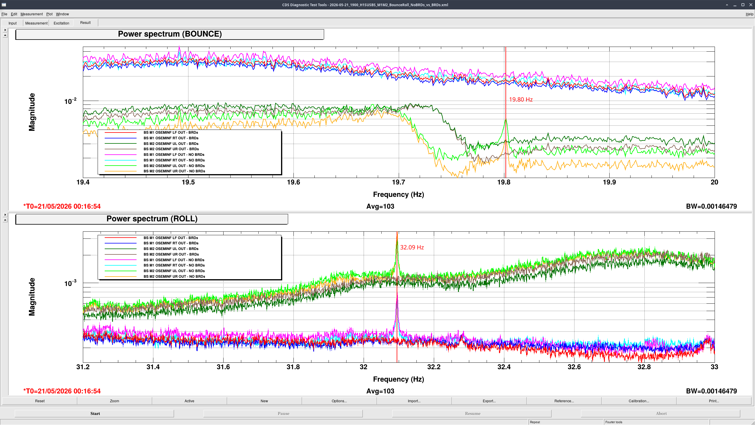
Comparison overnight spectra of the BBSS's M1 LF/RT and M2 UL/UR osems before vs after the installation of the BRDs is showing that the BRDs are correctly damping the Bounce and Roll modes and so don't need to be adjusted.
Bounce and Roll frequencies (measured before installing BRDs) were at 19.80 Hz for Bounce and 32.09 Hz for Roll. Final measurements will be taken in chamber.
No BRDs
- Brighter colors
- Overnight measurement taken over >14 hours
- Starting time: 2026-05-20 00:08:45 UTC
With BRDs
- Darker colors
- Overnight measurement taken over >14 hours
- Starting time: 2026-05-21 00:16:54 UTC
The data file I used for this can be found in /ligo/svncommon/SusSVN/sus/trunk/BBSS/H1/BS/Common/Data/2026-05-21_1900_H1SUSBS_M1M2_BounceRoll_NoBRDs_vs_BRDs.xml as r13015.
(Betsy, Jason, Oli)
Today Jason setup to see Pitch and Yaw of the BBS in the suspension cage on the cartridge. We were a ways off in Yaw and some Pitch. I spent a few hours walking YAW but the mechanics are rough. 5 bolts lock down the whole Top Blade assy and then you can use a push or a pull screw to pivot the whole Top Blade mechanism. Repeat for the second Top Stage blade assy. Of course when you pop the 5 locking screw the entire chain sags and grounds on stops yeilding confusing beams to look at. So a few iteration of this and that got us kinda no where. Part way thru I discovered that the push/pull thingy was totally out of range on both. No idea why. So back to starting over tomorrow and maybe trying to go around this "yaw" adjustment and just push the stages in the mounting slop or something.
Seems like I wrote this alog 10 years ago. Probably did since the mechanics from the BS are the same and we struggled with them at that time too. Will need to read back and also check how LLO faired with this.
Meanwhile, Oli and I also struggled to get Pit damping working so a few hours of parallel brain straining on that, swapping out the quad cable and it seems to be working. Weird tho because this is the same cable we used on the BS just a couple weeks earlier.
Yeah this yaw adjustment was no fun. Here at Livingston, it took us a decent part of a day but we think we got a good system going by the end.
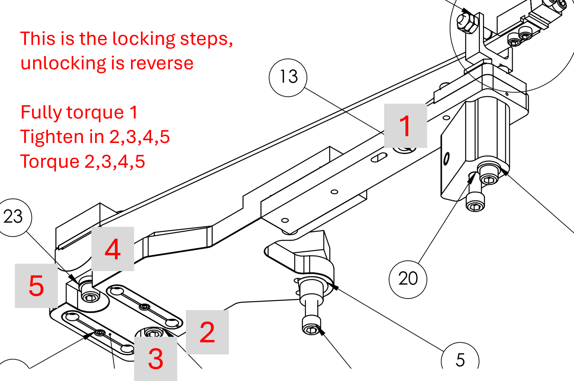
We adjusted only one side at a time. We tried to keep the way we unlocked/torqued the 5 bolts of the top blade assembly consistent (see photo attached). When we unlocked we tried to only get the bolts barely loose and back them out as little as possible. Each time we locked the 5 bolts down, we found that the structure moved around 0-4 minutes in a consistent direction. By following the attached photo procedure, the yaw seemed to settle consistently 2ish arcminutes off of its unlocked value in the same direction each time. For example, unlocked we would set the BBSS at 45 degrees - 5 arcminutes, and when we locked it down we would get 45 degrees - 3 arcminutes. We repeated the process until we got lucky and the suspension locked in the right place. This took a lot of trial and error. There is some hysteresis in the push/pull screw adjustment. The yaw adjustment is not very good or repeatable.
To make matters worse, the LF and RT OSEM plates have the circular inset that houses the disk that the magnet flag of M1 sits on. This is a place where it is very easy to get subtle rubbing and it is hard to verify by eye. We did this alignment with the QOSEMs which was somewhat of a blessing because the Y direction readback of the QOSEM can act as a guide to tell you if you should start to be concerned about rubbing. It might be worth removing the LF and RT OSEM plates and see if you can to the alignment without roll or vertical damping to avoid this rubbing. If the suspension is moving too much to not have V and R damping, you must frequently adjust the LF and RT OSEMS to ensure that there is no rubbing at that location.
Ibrahim, Oli
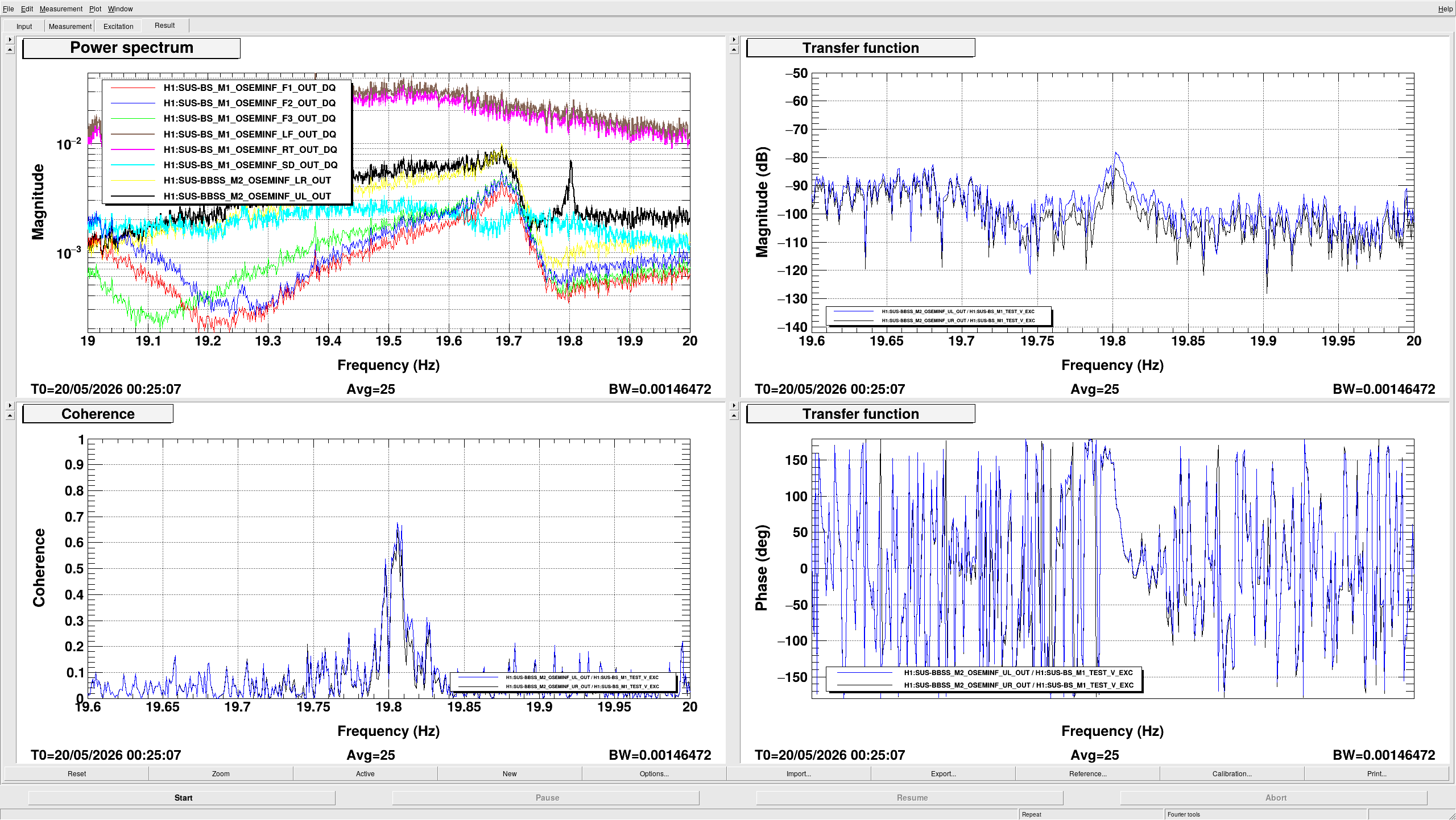
We ran a long overnight Bounce measurement on the BBSS. The BRDs weren't installed for this measurement. AOSEM flags were not installed, and we were 100g heavier at M1 than we are now (this measurements was taken before 90294).
With those settings in mind, our measurements show that our Bounce mode was at 19.80Hz. The last time these measurements were taken, back in the staging building (88141), the bounce mode with no BRDs was ~19.74Hz, so they're consistant.
The measurement file can be found in /ligo/svncommon/SusSVN/sus/trunk/BBSS/H1/BS/Common/Data/ 2026-05-19_2200_H1SUSBS_M1M2_BounceNoBRD_V_0p001to40Hz.xml as r13012.

Attached here is a zoomed in version of this file. The mode is indeed clearly visible in M2 UL, and the frequency is known well enough for proper BRD tuning. Thanks!
The Q of the mode seems to be about 3400. Maybe a higher excitation would be possible to get a better definition. Were you at the saturation limit to drive M1 V?
R. Crouch, J. Oberling, I. Abouelfettouh, O. Patane
As Ibrahim reported here, we have completed the first round of BBS position alignment (I say first round as we still have to do the pitch/yaw alignment, and that has the potential to change the position alignment so we may be doing this again). In the basis of our alignment equipment, which is set normal to the AR face of the BBS, the deviations from nominal are:
If we rotate these deviations to the XYZ axes using the BBS yaw we get deviations along those axes. I'm using the target BBS yaw for this (specifically, the AR surface yaw from the +X axis of 45.1056°), as we have yet to measure or align the actual BBS yaw, so this is more of an estimate at this point but will work for now (it takes a yaw change on the order of several degrees to change this calculation at the 0.1 mm level, so this is a pretty good estimate); this will be tightened up once we align the BBS pointing and revisit the positioning. The results (the tolerances rotate with the deviations, hence the change in X and Y):
The below table gives the target position of the center of the BBS's AR surface and the current position based on the above estimate of the XYZ deviations (all units are in mm):
| Axis | Target Position | Actual Position | Deviation | Tolerance |
| X | -160.4 | -160.5 | -0.1 | +/- 1.4 |
| Y | -226.3 | -225.8 | +0.5 | +/- 1.4 |
| Z | -83.1 | -83.2 | -0.1 | +/- 1.0 |
The next step in the alignment is to use the FARO to set up a total station/laser autocollimator combo looking along the target surface normal of the HR surface of the BBS. This will be used to align the BBS pitch and yaw. Once that is done we'll have to re-check the BBS position alignment (again, using the AR surface of the BBS) to ensure the pointing alignment did not change the optic's position (which may happen in this case as the BBS is currently, as Ibrahim reports, "quite yawed").
Ibrahim, Oli, Jason, Ryan C
Work done today:
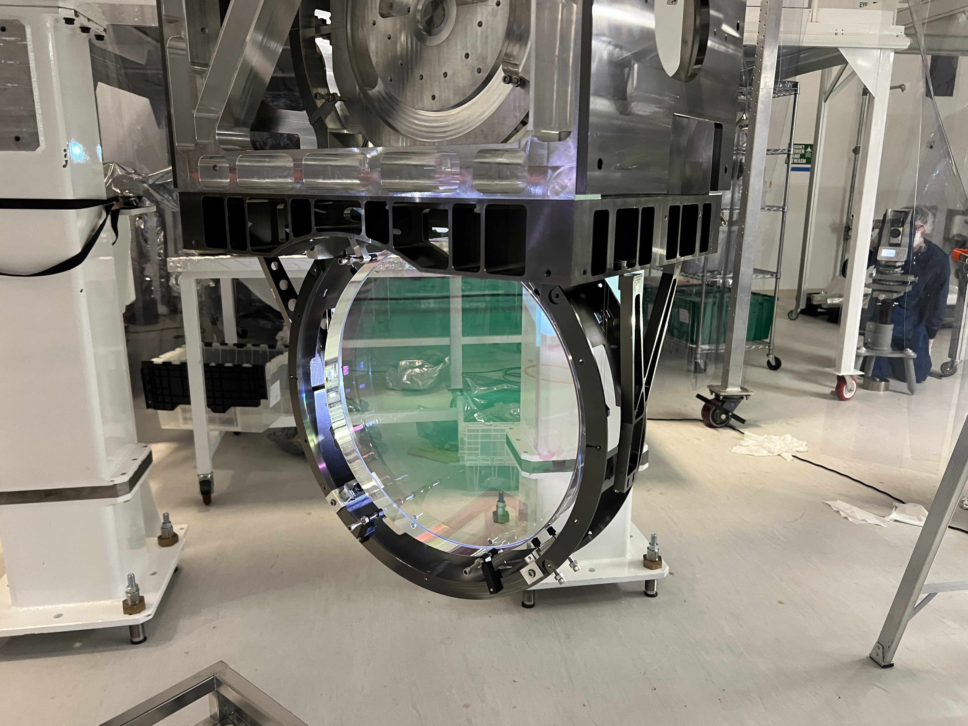
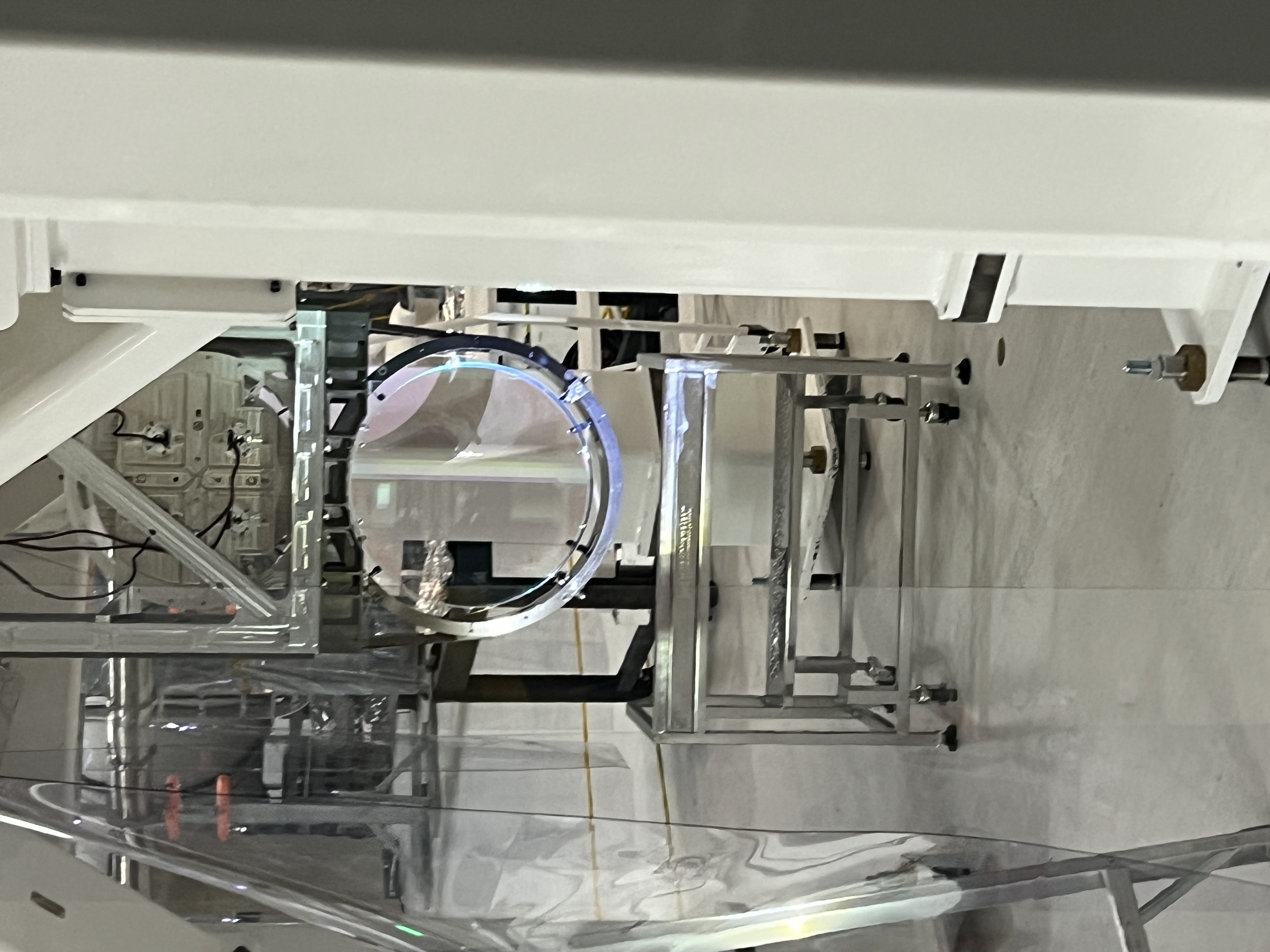
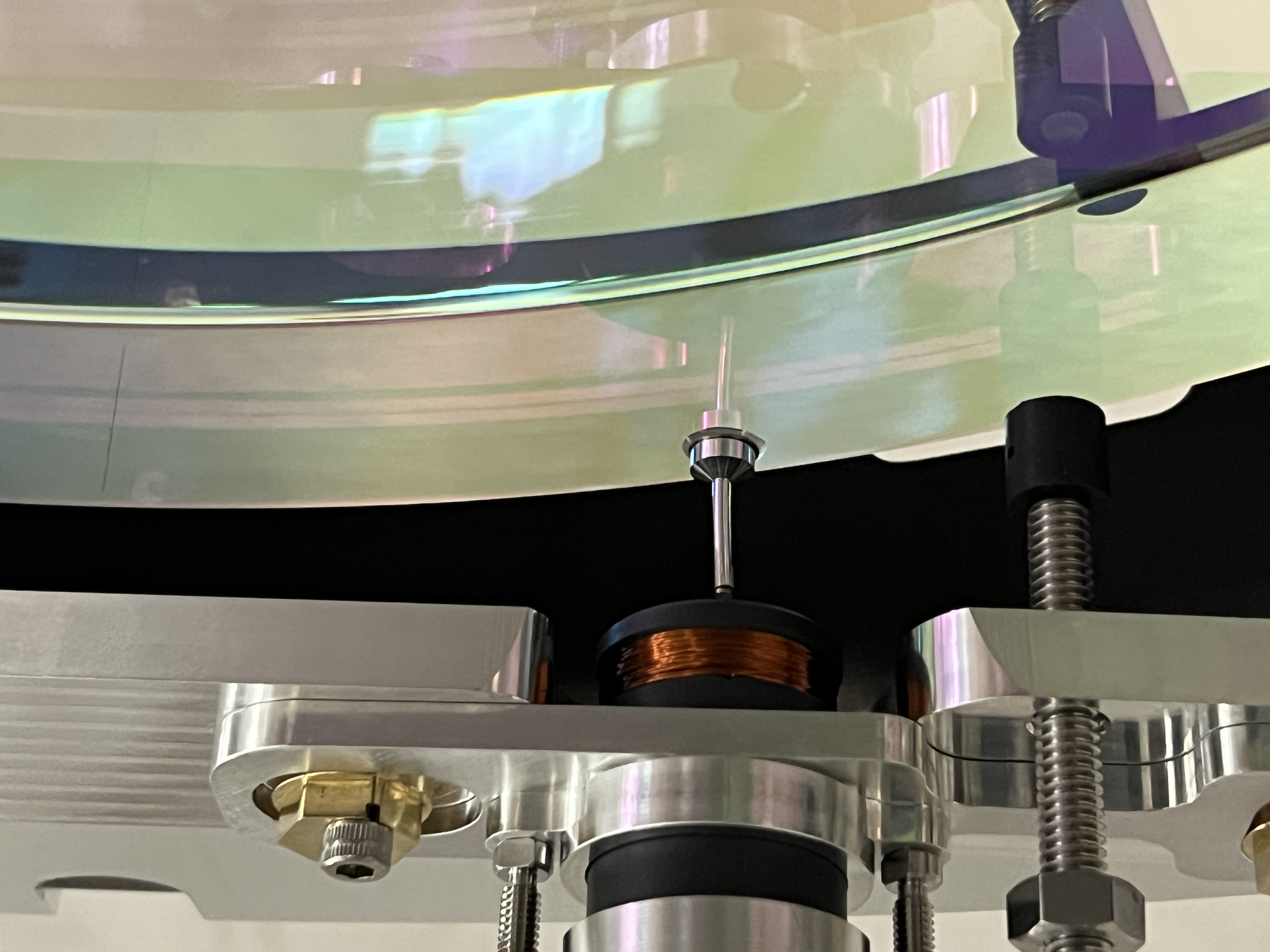
Specifics of Optic XYZ Alignment
See pictures below.


Conclusion: T2000599-v6 (r13010) of bbssopt.m matches LHO parameters, T2000599-v5 (r12764) matches LLO's current configuration, but the difference in the models is negligible
The M3 mass listed in the bbssopt.m parameter set has been changed from 20.99kg to 20.909kg to match the mass of LHO's BBSS M3 optic.
This mass is given by the mass of the optic itself (20889g) + the mass of the primary prisms (7.56g and 7.46g) + the mass of the secondary prisms (5.57g together). This gives us 20.909kg. The change in the model from this is very minimal - the highest Pitch peak shifts down by a few hundreds of uHz, from 1.1656Hz to 1.1615Hz.
LLO's BBS02 is 21.065kg, and comparing this to the previous dummy's mass, the peaks are still in the same place, so the previous version of the model, v5 (r12764) matches with their current configuration, but since the shift is so minimal, using the same model that LHO is using would be fine.
I've updated T2000599 to -v6, and committed /ligo/svncommon/SusSVN/sus/trunk/Common/MatlabTools/TripleModel_Production/bbssopt.m to r13010.
The comparison for all DOFs for all three mass changes can be found at /ligo/svncommon/SusSVN/sus/trunk/BBSS/Common/Results/comparetripleparams/2026-05-20_M3_DummyvsLHOvsLLO/triplemodelcomp_2026-05-20_M3_DummyvsLHOvsLLO_M1toM1.pdf and committed to svn as r13011.

R. Crouch, B. Weaver, I. Abouelfettouh, J. Oberling, R. Thompson
Today we placed and aligned the BBS SUS cage on the WBSC2 ISI. In the morning we rough placed the SUS, and thought we had done a really good job on the first attempt. However, that was fed by a misread of how the Build/Inspect function in PolyWorks, well, works, and upon doing a more thorough measurement (directly measuring a constraining plane to inform SMR radius compensation instead of letting PolyWorks handle it automatically) we found there was a position and rotation error to the cage.
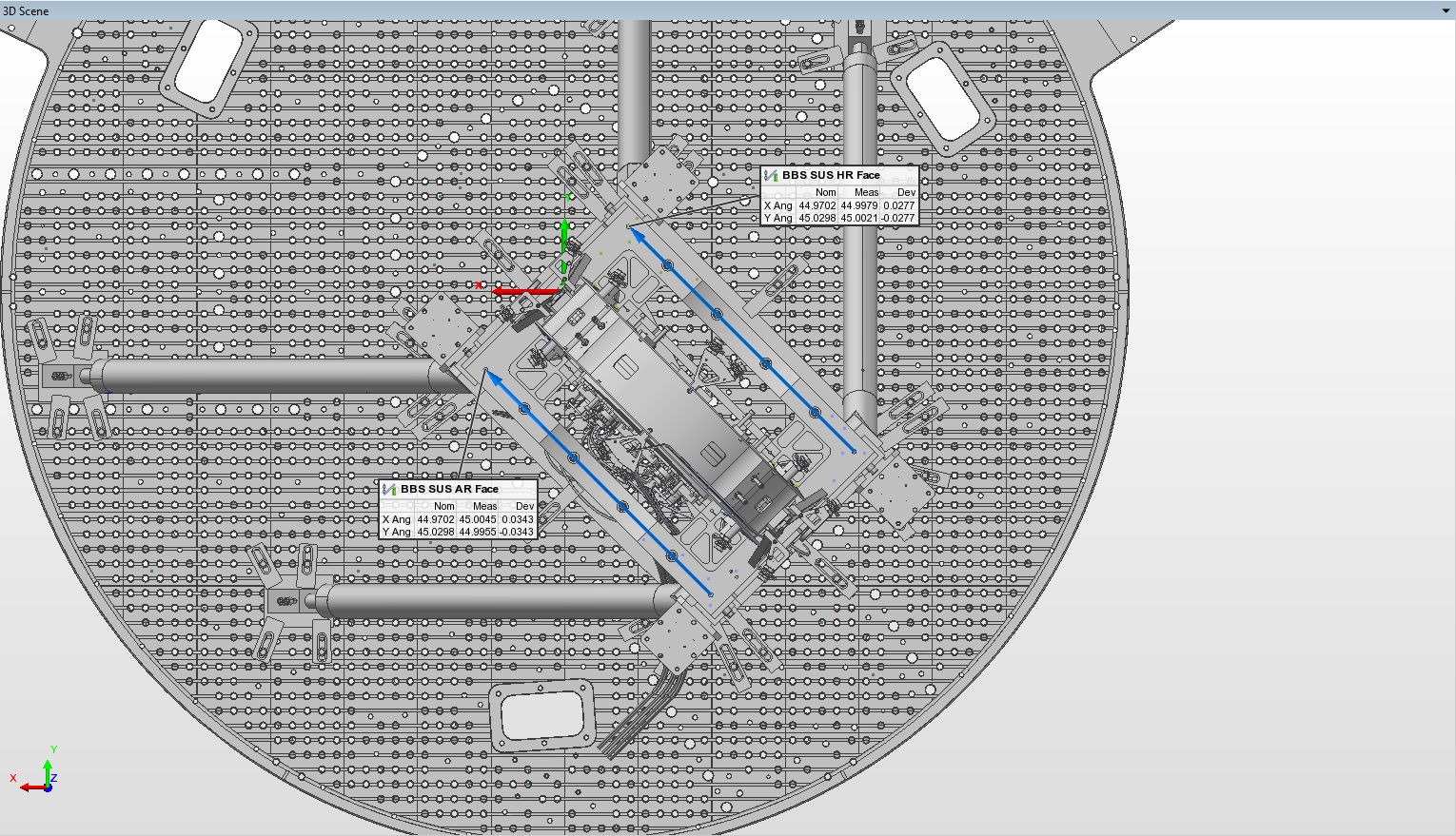
In the afternoon we moved the SUS cage around until things looked really good. We were well within our +/-1.0 mm XYZ tolerance, but once the SUS had been fully dog clamped to the ISI things shifted (as they do). In this case, it was roughly 0.5 mm in the +Y direction. All of our measurement points except one are within tolerance, so we called this good enough for SUS cage placement. To end, Ryan and I measured the circle that's defined by the lower section of the Figure 8 (the round section of the SUS cage that surrounds the BBS) on both the HR and AR sides of the cage. The first attachement shows the position deviations of the 4 points we used for cage placement/alignment and the current position of the HR and AR Figure 8; all except the Y axis position of 1 point are within our tolerance. The second attachment shows the rotation of the SUS cage w.r.t. the ISI; the angles listed are in degrees and are measured from the positive axes they are associated with (so X Ang is measured from the +X axis). These 2 lines show that the SUS cage is rotated roughly 400 - 500 µrad CCW (top-down view) from nominal.
Next up is to set up a total station looking at the AR face of the BBS to precisely align the optic to the ISI.