
REMOVE SEARCH FILTER
SEARCH AGAIN
Search criteria
Section: H2
Task: SEI
The CS HEPI system is planned to be upgraded to a Beckhoff PLC system. Modifications to the motor control panels to readout the VRD readback signal completed. Cabling and panel connections cleaned up. Part of ECR E2200043.
Prior to starting work:
[Shoshana, Ryan S]

Yesterday we began building the second set of CRSs sent over from LLO (mostly just putting in heli-coils). I (Shohana) will probably continue working on them today

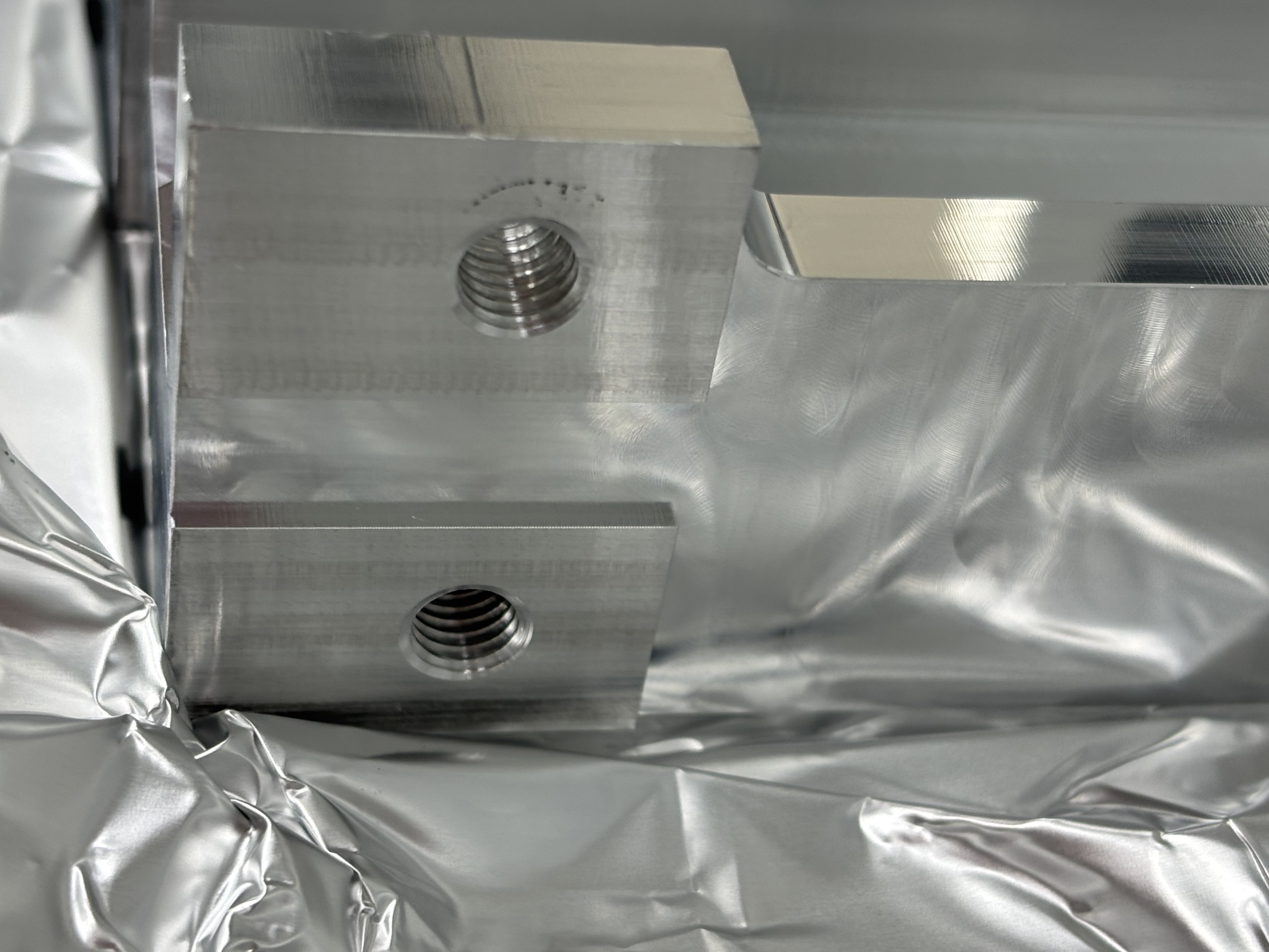
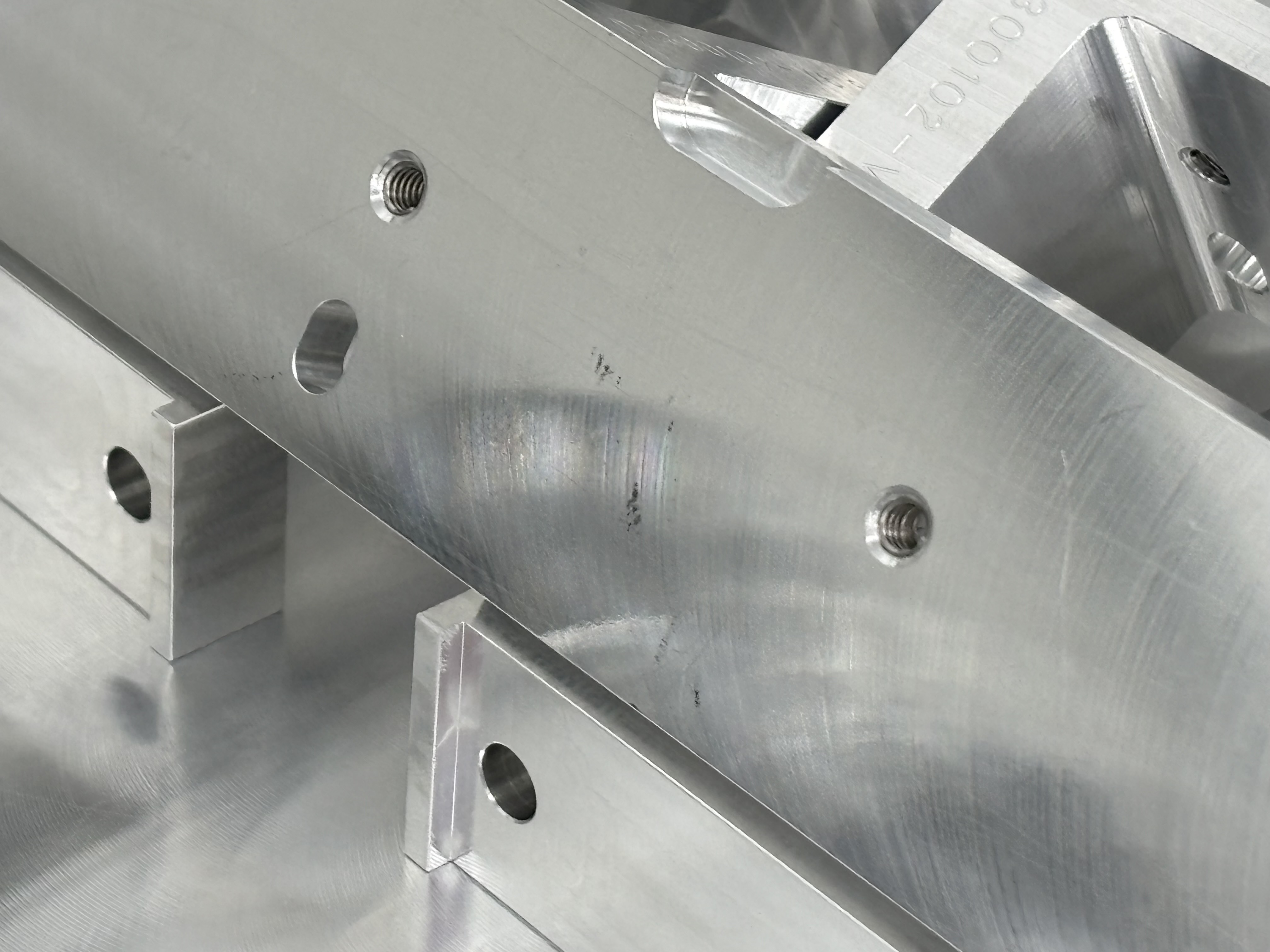
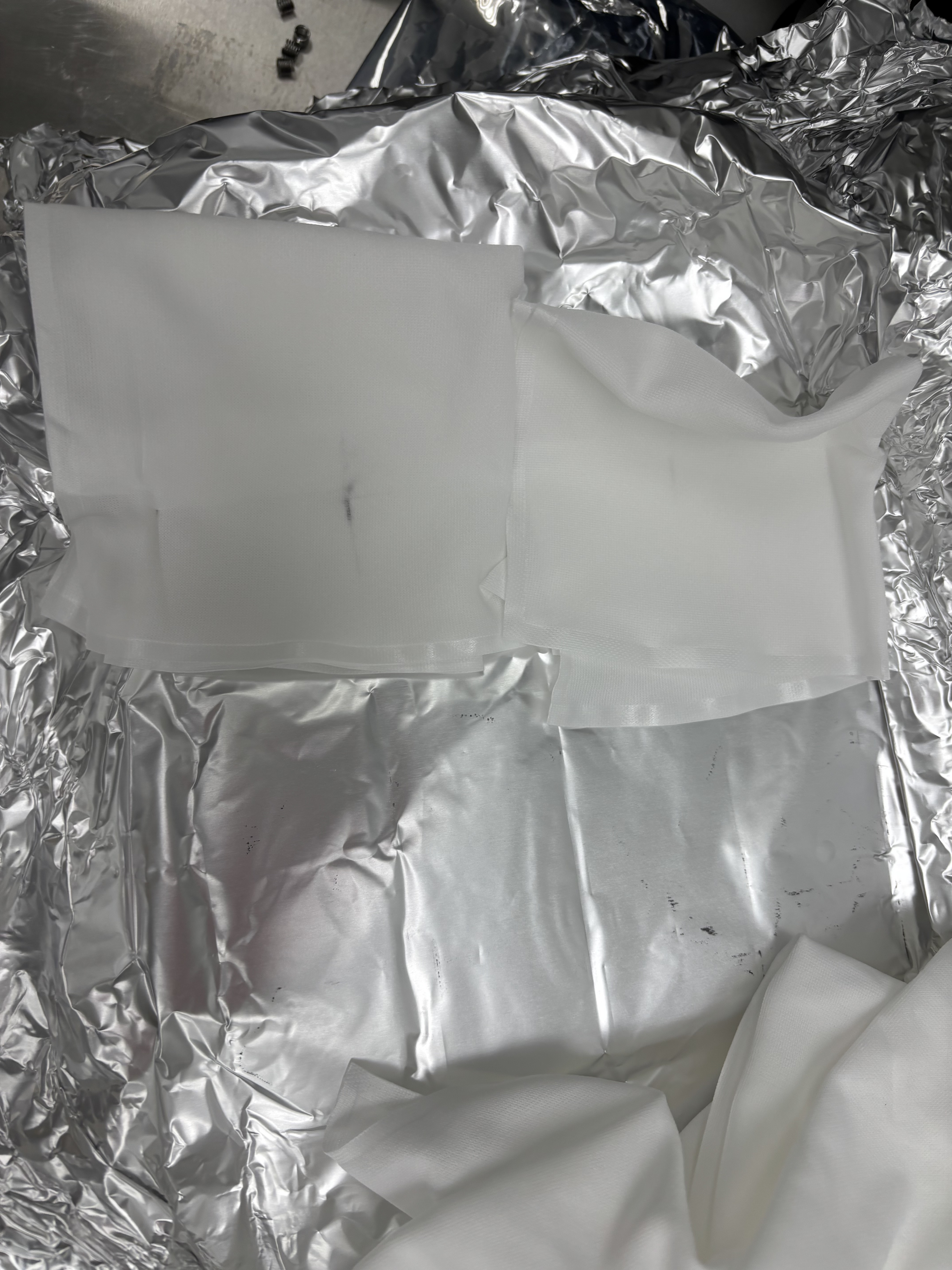
For some of the parts sent over from LLO (where they had already gone through clean and bake) we found some black residue in some of the aluminum foil wrappings and on the parts (specifically the cross beams [D2300102] and the solid supports [D2300144]) some of which would come off when wiped, but some of the residue would not. Pictures below

[Shoshana]
Continued LLO CRS build
One of the CRS Legs [D2300089 SN016] has a threaded hole on the side where the threads do not go deep enough for a helicoil to be fully inserted, and ends the helicoil up sticking out by ~1/8 inch, meaning half of one of the CRSs cannot be fully built right now unless the hole is tapped deeper a shorter helicoil is used.
There were no other issues and 1.5 of the extra CRS supports are built

The clean and bake team at Livingston says the residue is just aluminum oxide and not an issue
Which threaded hole is it ?
If the hole depth is correct, but we're just missing the threads on the bottom part of the hole we can tap it with a clean tool.
Alternatively we can also order a 1D helicoil.
J. Kissel
E2600106 / IIET:37433
D2400107-v4

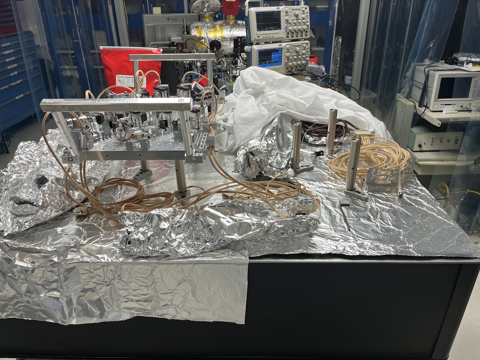
I've decommissioned the SPI pathfinder's ISIK Transceiver as it stands now (D2400107-v4) by
    - disconnecting all electronics cabling; PDs at the cable-table bracket and picomotors' quadrupus at each pico-actuated optic
    - disconnecting optic fibers
    - untangling the in-vac cabling and fibers, ensuring the
    - installing installation handles (LHO:90223)
    - setting up a new set of 1"D x 6"L class-B posts then
    - removed the 3x temporary class-B bolts and washers that had secured the breadboard to the posts
    - lifting and transferring the D2400107-v4 assembly over to the other position and
    - securing there with the 3x temporary class B bolts.

Pictures of the move attached.

J. Kissel, J. Warner
ECR: E2400026
WPs: 13237, LHO:13238
Final Design Doc: T2400145
Relevant Systems Level Drawings:
    . Mechanical Assemblies
        :: ISIJ Reflector D2400102
        :: HAM Table Baffles D1700335
        :: HAM2 Systems Layout D0901083 (not yet-inclusive-of-SPI)
    . Electronics Wiring Diagram
    . Cable Routing In-vac Cable Routing Plan from G2401479 (pages )
    . Flange Layout D1002873-v11

Executive summary:
    - Removed ISIJ +X-side, center, HAM2 ISI table baffle from D1700265-v4 Type 2
        :: Bracket mounting bolts left screwed into ISI optical table for this will eventually become a D1700265-v4 Type 3 and remounted.
    - Installed ISIJ Reflector + QPD Assembly D2400102 on +X ISI side wall (D071057-v2), with its shroud (D2500030) in place
        :: We didn't weigh it, but the SW Assembly predicts a mass of 1.96 [kg], which we can likely round up to 2.0 [kg] with the shroud installed.
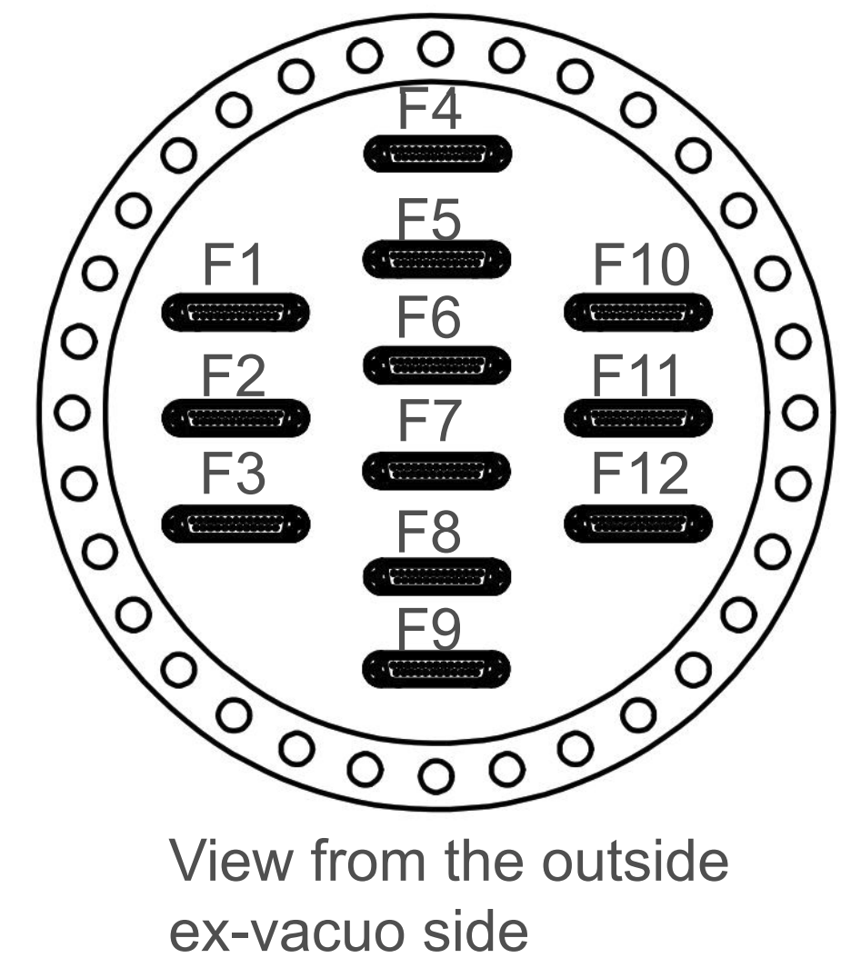
    - Routed and connected QPD read-out cable system to D3 flange, F10 spigot.
    - Routed and connected picomotor cable system to existing D1101515 quadrupus leg Cable #3, J4
        :: Cable #4, J5 is connected to IO PM5 mirror, Cables #2 J3 and #1 J2 were reset in neat coil with connectors floating to avoid electrical grounding as before.
    - Nudged make-shift baffle system using D1700261 ballast mass baffle mounted vertically on the +X / +Y / Beam Height corner of the chamber wall upon entry into beamtube.
        :: the will DEFINITELY need a technically-minded reset.

In at 10:30a PT and out by 12:30a PT. It's so lovely when everything goes to plan!

Pictures and further info to follow in the comments below.
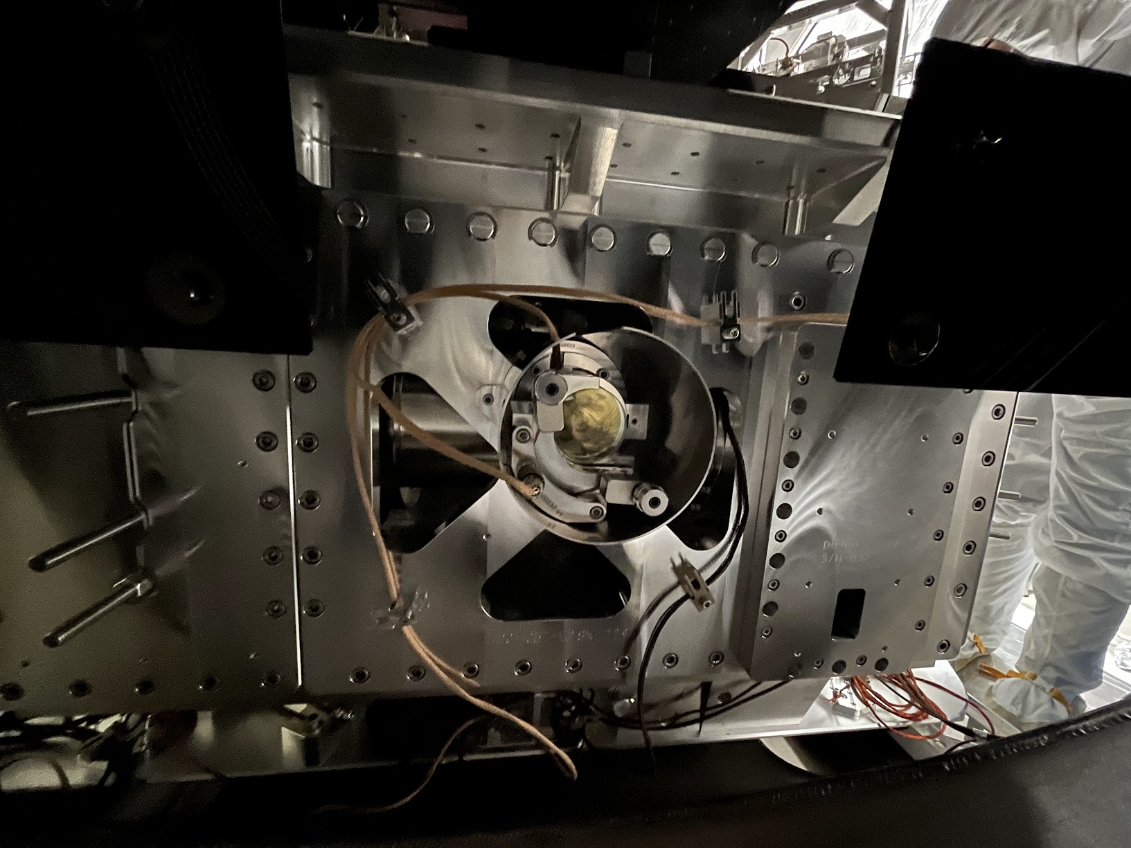
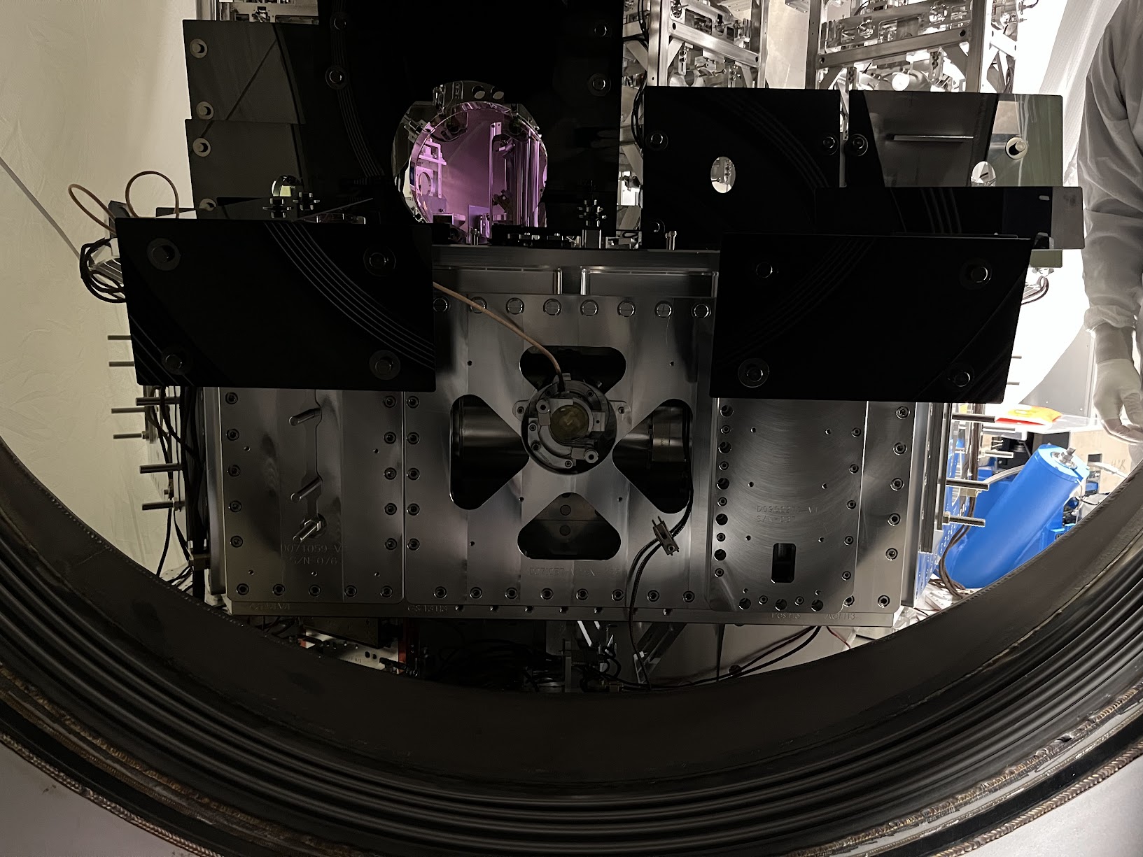
Removing Center ISI Table Baffle

Not much to say more here -- removal was easy. We tried "just" removing the panel using the the coated/capped screws, but these didn't budget upon several attempts with Jim's fingers and grunts. So, elected to fight that battle outside the chamber and removed the whole assembly at the table mounting point.

The full assembly is wrapped in dry-wipes, foil, and ameristat bagged and in Mitch's office while it waits for the Type 03 version of the panel to come out of clean-n-bake.
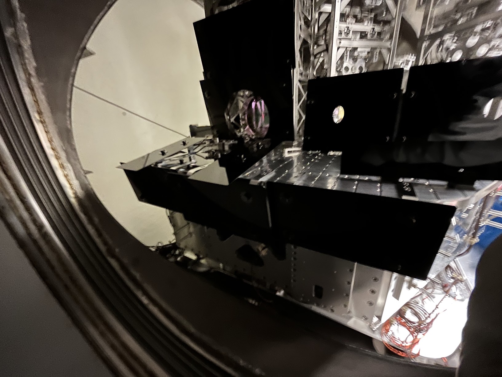

Installation of ISIJ Reflector itself

Also not much to say, other than the great joy that the drawings of the D071057-v2 ISI Side Wall have the irregular positions of the 1/4-20 utility holes accurate enough that Bram's CAD-informed-only mounting holes for the ISIJ reflector's baseplate of the reflector lined up without issue. *phew*

Also -- the D2400102 drawing doesn't highlight which length 1/4-20 bolt should be used for mounting, so we used 1/4"-20 x 0.625"L (5/8"), which was "just enough."

Pictures from the main entry are the best "big picture" views, but here I attach a few more in case the need arises.


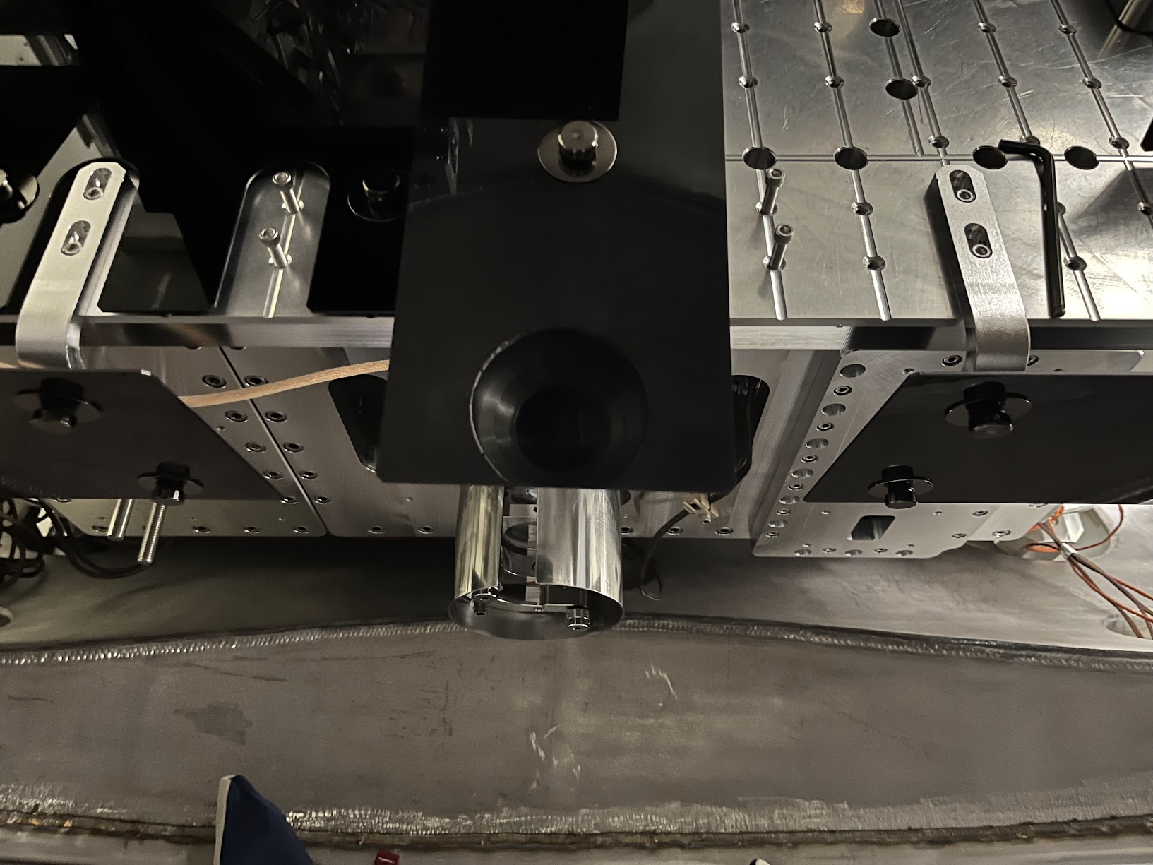
QPD Cable Routing

We didn't get dedicated pictures of this QPD cable routing but,
    - it follows the plan on page 22 of In-vac Cable Routing Plan posted to G2401479-v3,
    - You can see the ST1 portion of it well-enough in the above pictures,
    - Jim did the routing, so I trust that there's a healthy loop in the jump from ST1 to ST0, and
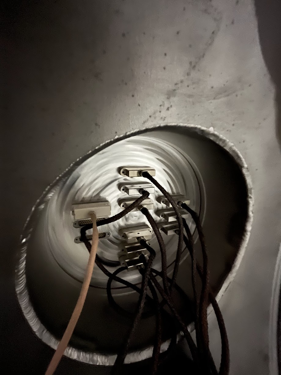
    - I attach a picture here of the record that we've connected it to D3-F10, and a copy of the "F-Type" (D2000225-v1) counting from page 18 of the above mentioned cable routing plan.
Picomotor Cable Routing BEFORE INSTALL

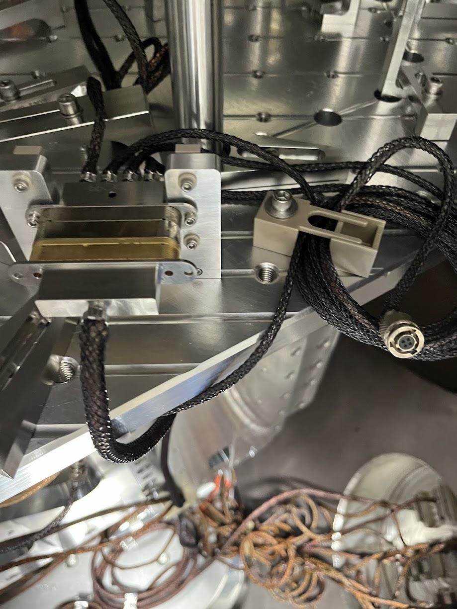
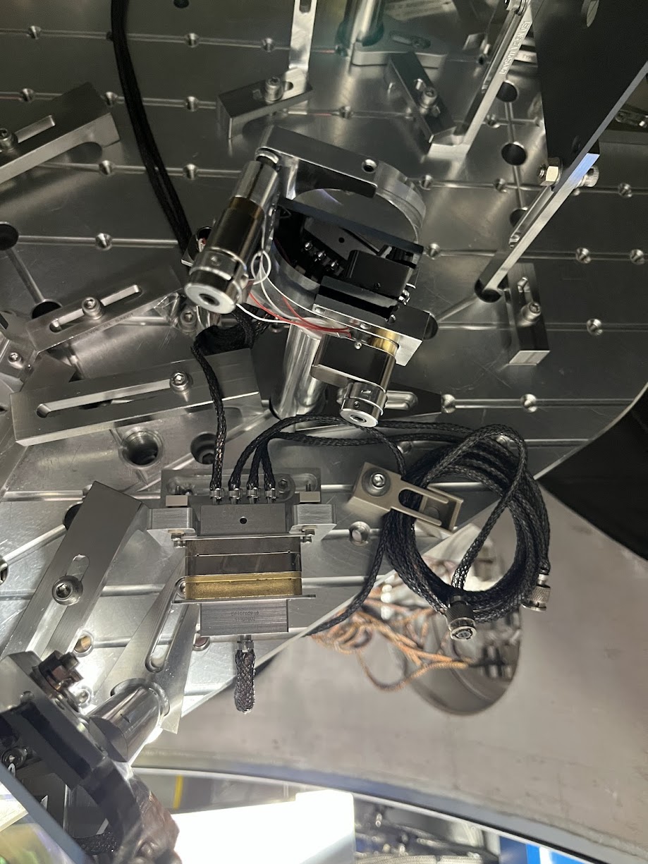
Just because we knew little about the details of this cable system ahead of time given how ancient the PM5 picomotor actuated mirror system, I got a lot of good "before" pictures. Mostly, I confirm that PM5 does use the Cable #4 J5 leg of the D1101515 quadrupus, and all the other legs were neatly cable-tied up and away.
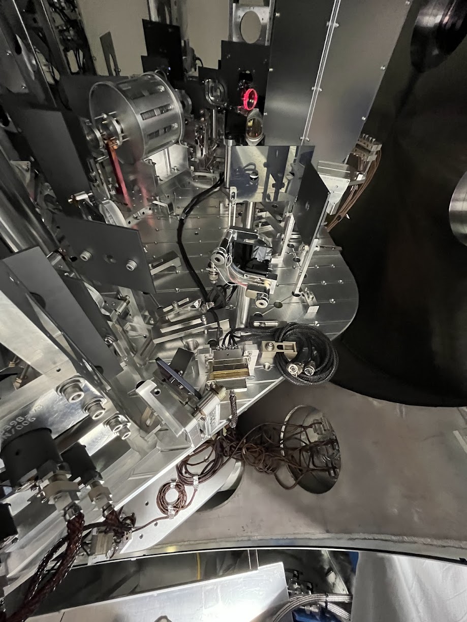
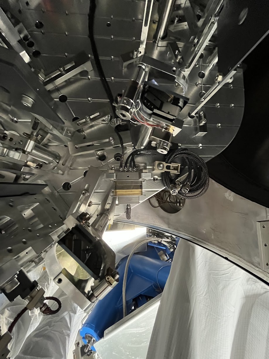
Picomotor Cable Routing AFTER INSTALL

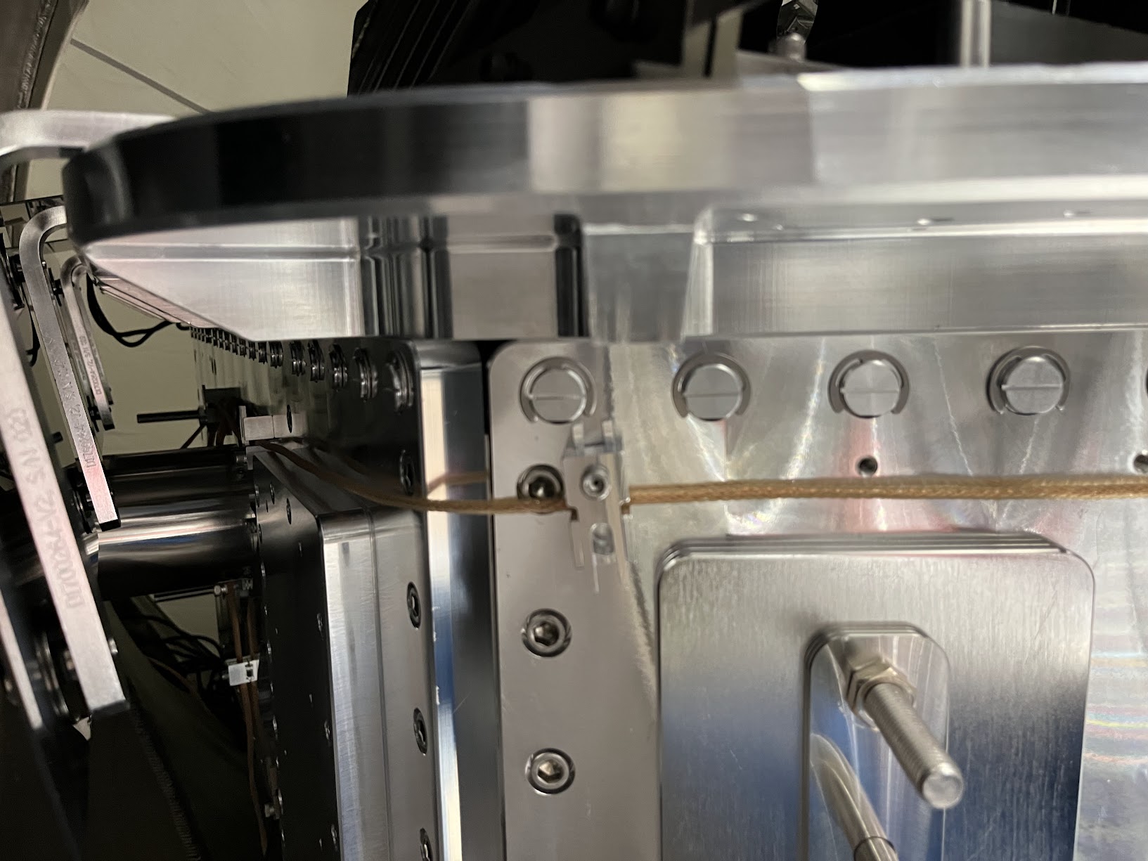
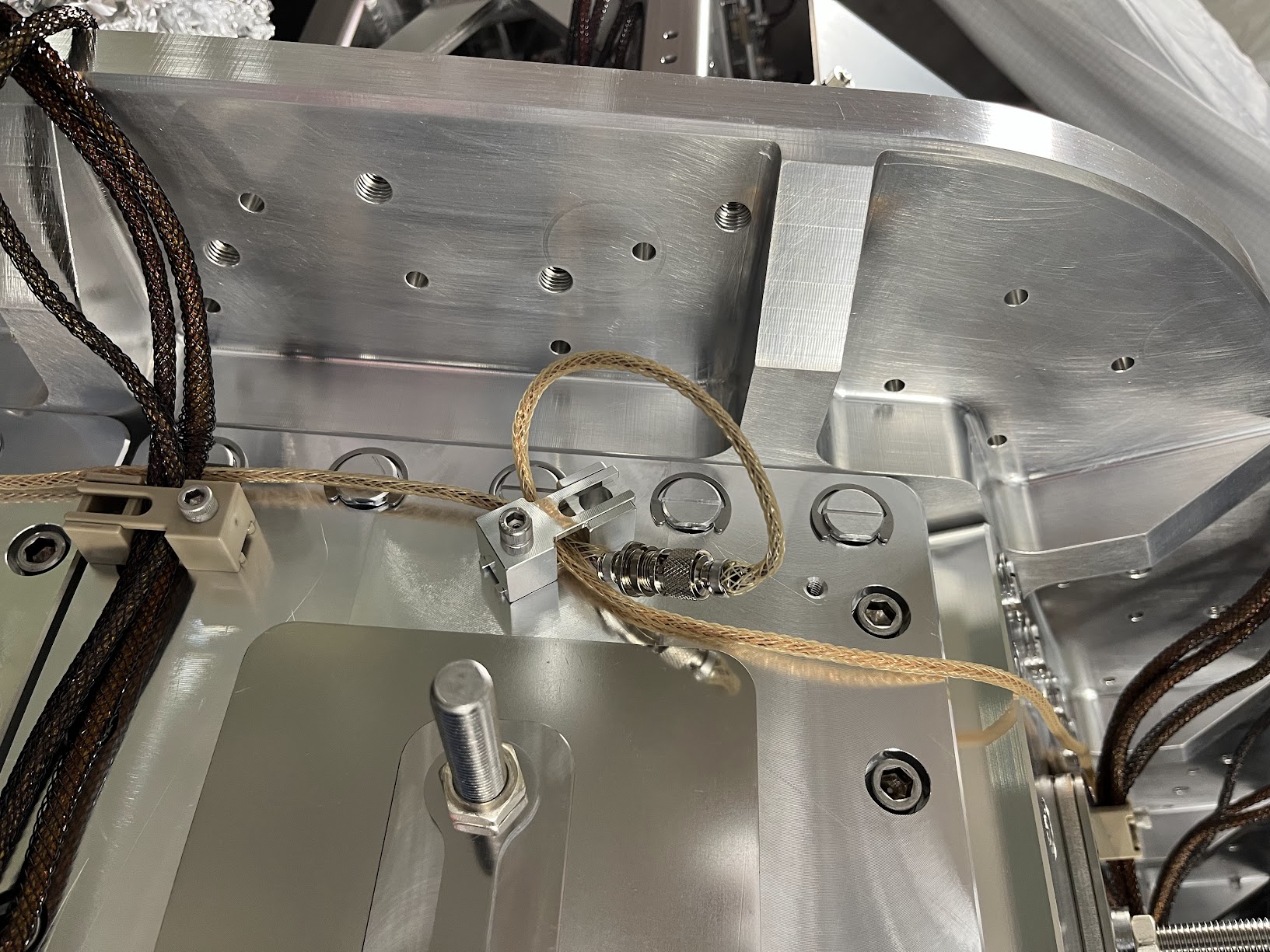
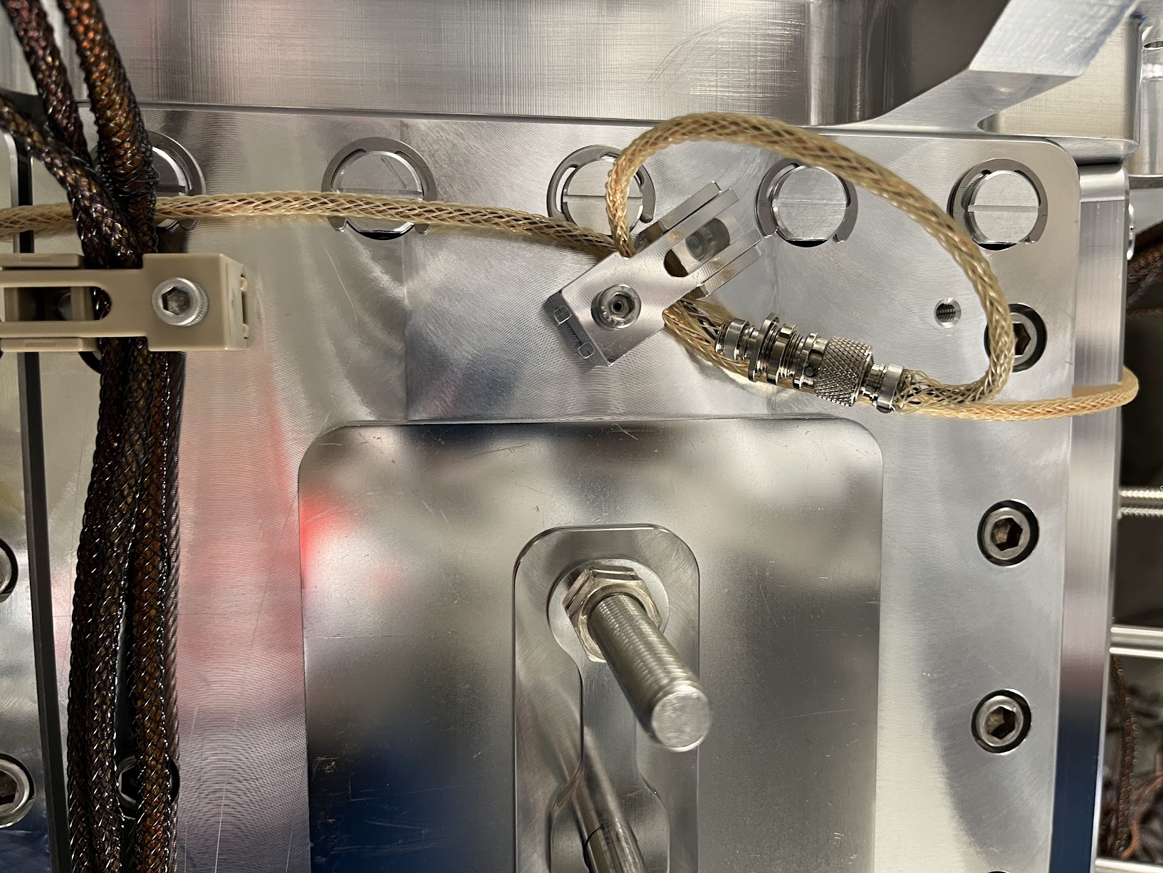
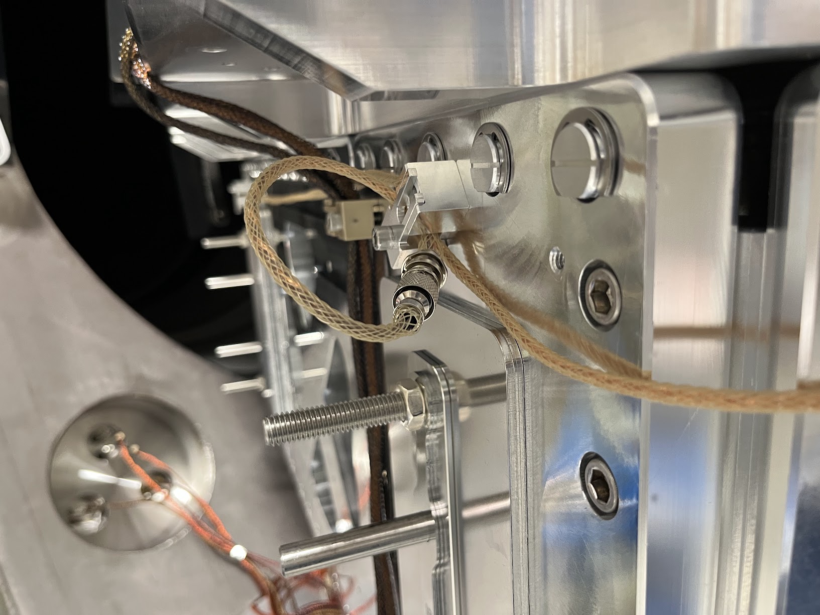
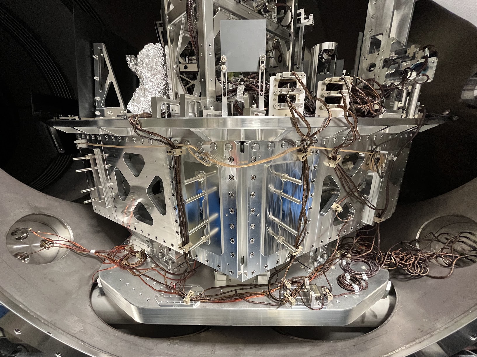
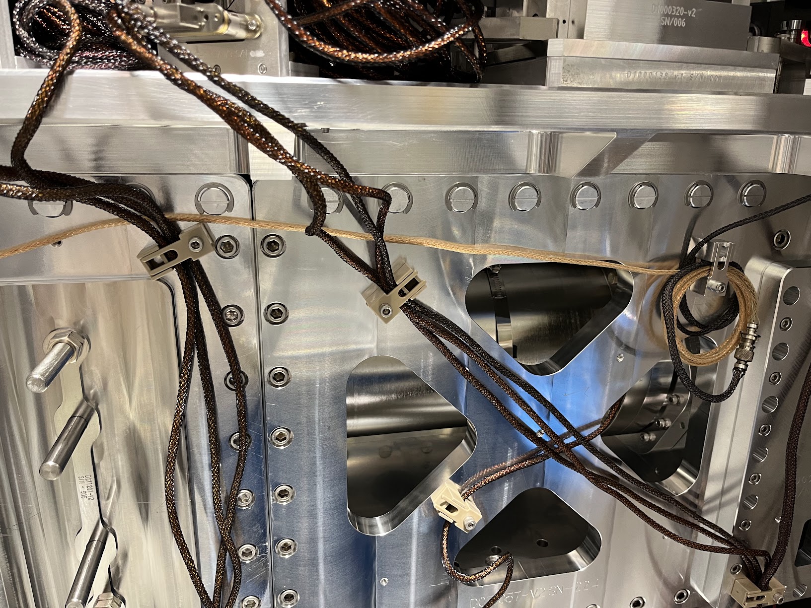
Here're photos of the routing of the two 72 [in] length D2400316 picomotor extension cables connected in series and routed to all the way around from the ISIJ reflector on the +X face to the -X / +Y corner of the table where CB-9 and the D1101515 quadrupus lives.

I paid particular attention to the connectors and made sure they were left floating and not shorting to anything metal.

I also re-bundled up Cable #2 J3 and Cable #1 J2 in coil similar to the before pictures, again ensuring that the connectors are floating in both space and electrical connection.



The Nudged Chamber Wall Baffle

Some pictures of the baffle that we nudged that will likely need re-alignment.

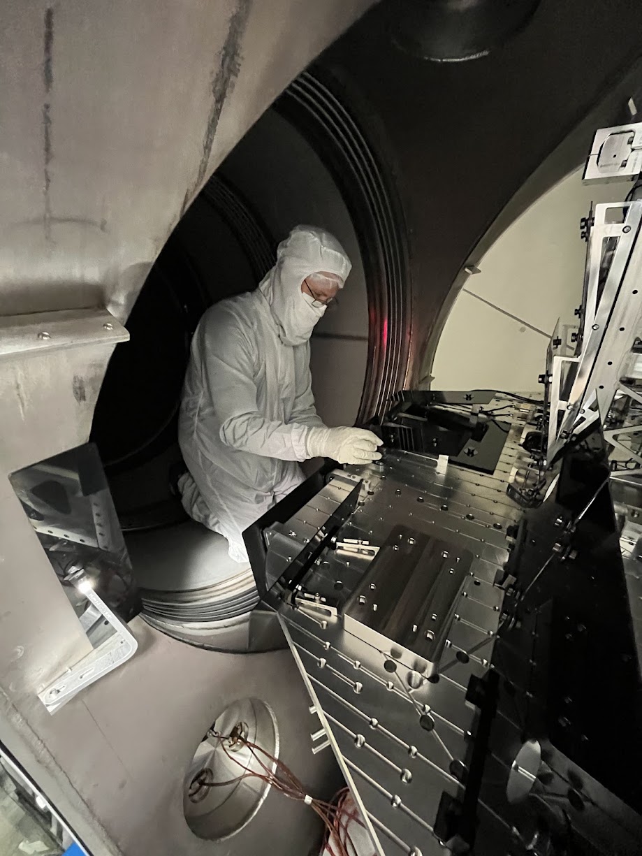
tagging for photos.
On the new channel assignment of HAM2's SPI ISIJ picomotor, and why I'm confident it's CH7:

Per D1000581-v13, page 13 and then D1900511-v12 page 17, I'm quite confident that the quadrupus cable and up in CH5-8 of the controller on IOT2L, called "PICOMOTOR 5" in D1900511, which I guess becomes "Picomotor B / Slot 2" on page 2 of the ECAT System Diagram D1100683-v11.

This is corroborated with opening up the picomotor MEDM screen -- sitemap > LSC > picomotors > "HAM 2 + oplev" button (that has "controller 5" and "PICO B" next to it), and clicking through the channels and seeing that CH8 is called "PSL ISS QPD/PD (PM5)."

Here's a labeled picture that makes things more clear.
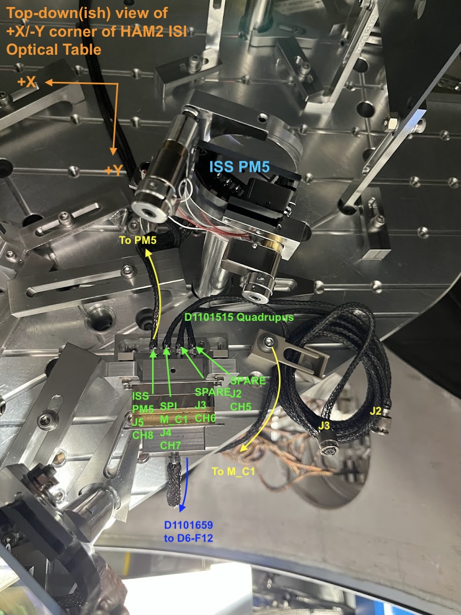
Belated aLOG on in-vac cable routing of the ISIJ QPD A PD and serial number assignments:

Path       PD Name    PD SN          Monopus            D9-to-D25 Monopus
                      |----------D2600002--------|
                      D1600083 Type 3     D2400340      D2300128
OL ISIJ    QPD A      S2401092            S2500517      S2500511

As of 20:05 UTC, the cartridge from BSC2 (including the soon-to-be-decommissioned beamsplitter) has been placed on the test stand in the LVEA West bay. The cartridge was first lifted at 19:15 UTC before making its slow procession across the LVEA via the 5-ton overhead crane. More details and documentation to be posted later.
J. Kissel

After the install of front-end software (LHO:89777 and LHO:89919) the next step for SPI is MEDM screens -- the UI/UX for the SPI L interferometers and PY one-way optical levers.

Here, I post screenshots and corresponding userapps svn file and location.
Sub-screens and their future purpose will come in the comments, but make sure to also check out G2402138.

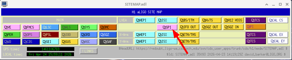
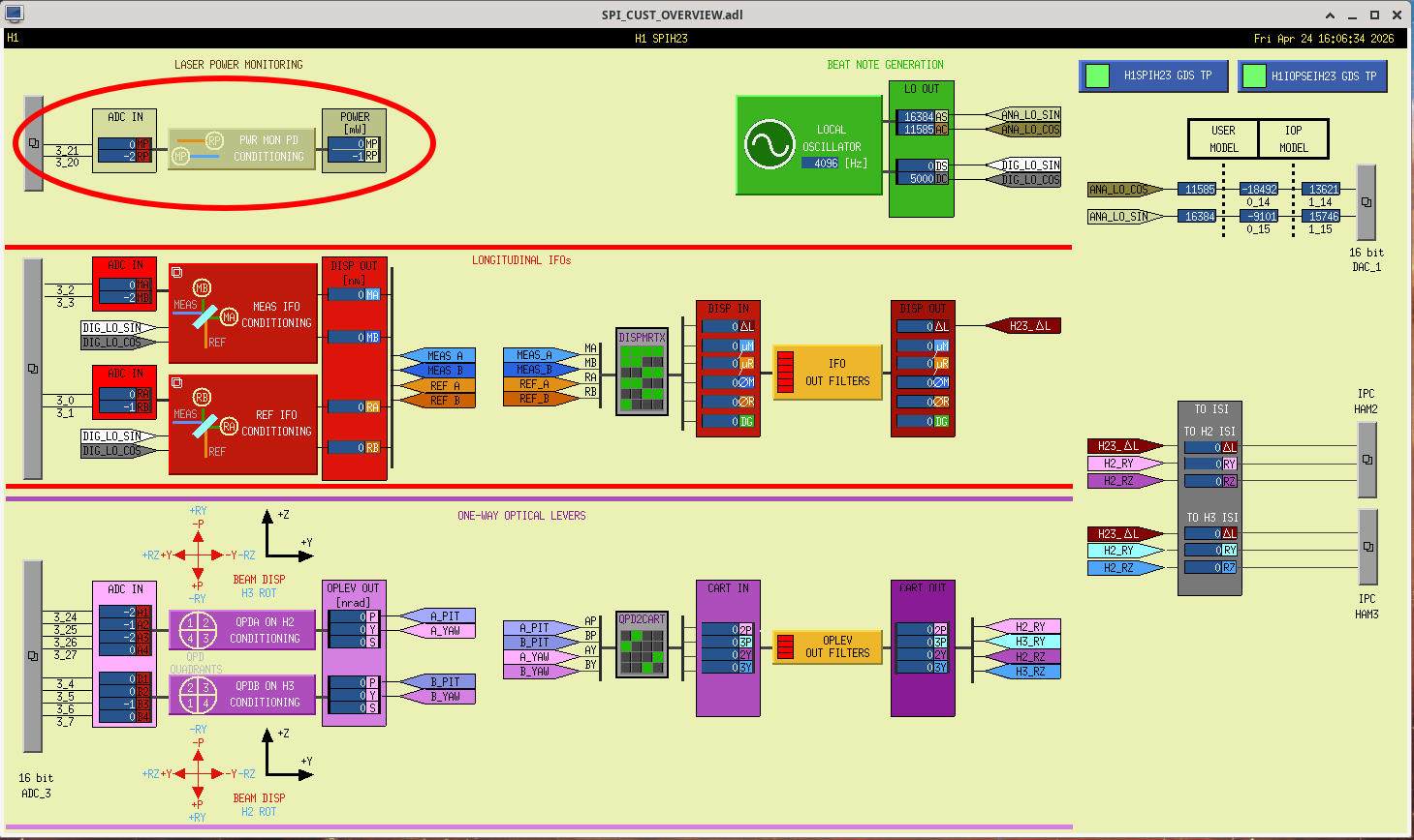
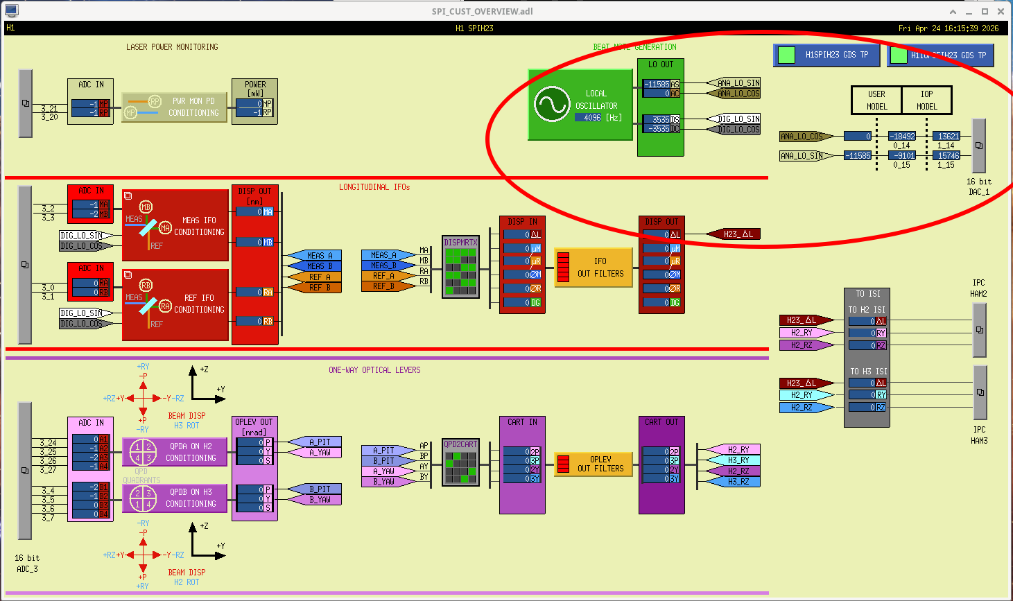
In the main entry, I show off the new place that SPI lives on the LHO sitemap and the overview screen.
The overview screen, and all subordinate screens use a marco file, which I also attach.

All of these files are, of course, properly version controlled in the userapps SVN, here:
OVERVIEW SCREEN
    ${USERAPPS}/spi/common/medm/
        SPI_CUST_OVERVIEW.adl        rev 35102

MACRO FILE
    ${USERAPPS}/spi/h1/medm/
        h1spih23_overview_macro.txt  rev 35106

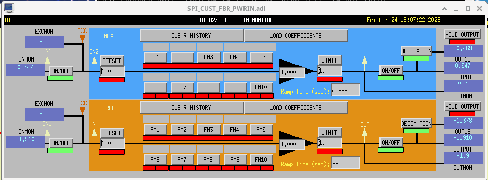
POWER MONITORING

These cover the on-board power monitor SPDs. Eventually, we'll use these filter banks to calibrate the PDs into [mW] as it lands on the ISIK breadboard.

${USERAPPS}/spi/common/medm/SPI_CUST_FBR_PWRIN.adl     rev 35102
LOCAL OSCILLATOR

The SPI's longitudinal IFO that measures the differential displacement in the main IFO's X direction release on heterodyne interferometry, with the interference between two beams modulated at 80 MHz and (80 MHz- 4096 Hz) = 79995904 Hz, which creates a beat note at 4096 [Hz]. 80 MHz comes from the site's RF distribution system of 80 MHz. The 4096 Hz is initially digitally generated via CDS, and a copy of that is sent out via DAC to be subtracted from 80 MHz with our homegrown single-sideband mixer, a.k.a "double mixer" (D2400315). This is the screen that controls the parameters of the cds oscillator, as well as some phase rotators and filterbanks to condition the digital LO into an analog signal for the DAC.

Nominally, the cds oscillator clock emits a 1 [count] amplitude wave, and the CLKGAIN, SINGAIN and COSGAIN parameters are set arbitrarily high, since its use as the LO for digital demodulation is usually entire internal to CDS. However, because this LO goes somewhere into real electronics, I've set the calibration of the signal condition filters such that the CLK, SIN, and COS gain are in units of [mV/ct] -- and I've set the LO amplitude at 5000 [mV] = 5 [V], mid-range of the DAC.

Since we don't yet know the right phasing, all the phase rotators are current set to 0 [deg].

${USERAPPS}spi/common/medm/SPI_CUST_LO.adl    rev 35103


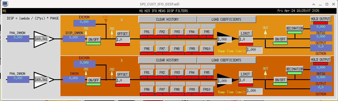
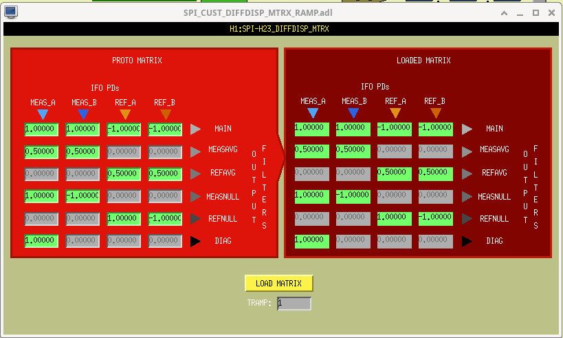
INTERFEROMETERS

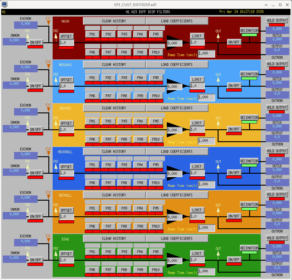
Here're the screens (less commissioned) that cover the digital demodulation and conversion to differential displacement.

${USERAPPS}spi/common/medm
    SPI_CUST_IFO.adl
        SPI_CUST_IFO_DEMOD.adl
        SPI_CUST_IFO_DISP.adl
    SPI_CUST_DIFFDISP_MTRX_RAMP.adl
    SPI_CUST_DIFFDISP.adl

all commited to rev 35102


ONE-WAY OPTICAL LEVERS

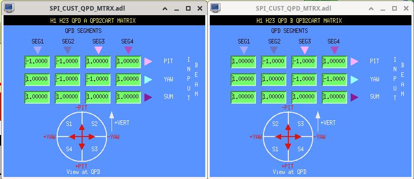
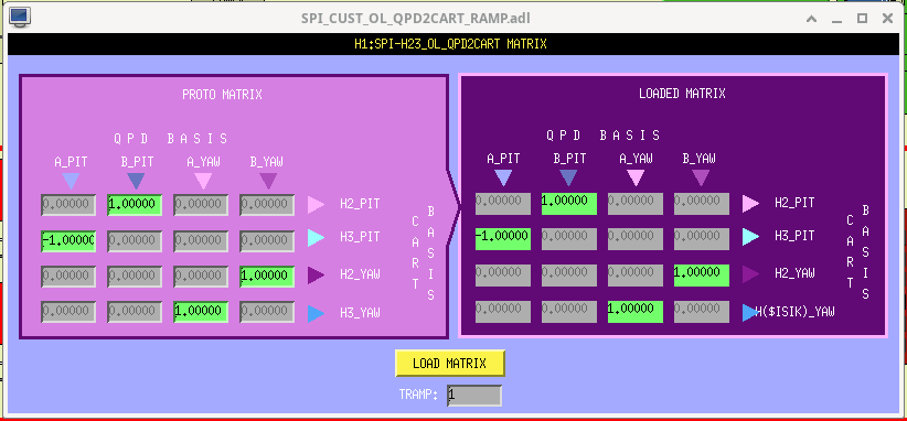
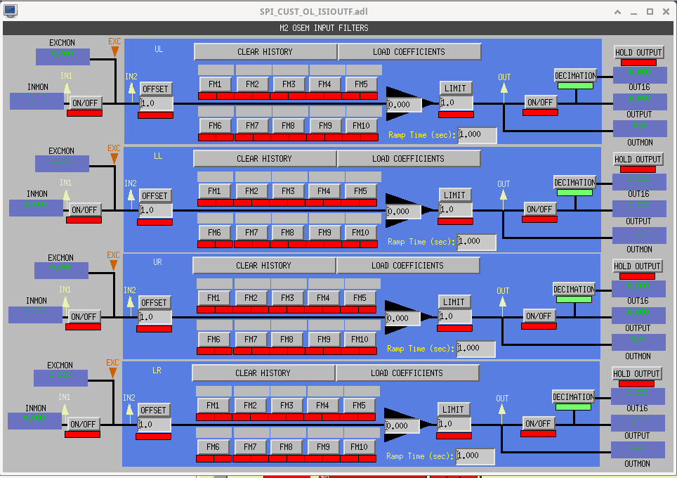
Here's the signal chain for the one-way optical levers. There's a good bit of confusing basis changing happening given
- the orientation of the QPD segments w.r.t. to vertical being different on HAM2's ISIJ QPDA and HAM3's ISIK QPDB,
- The usual conversion from QPD segments to pitch and yaw, as the beam flies, then
- Converting from beam pitch and yaw to ISI rotation, given that the HAM2 QPDA measuring HAM3 rotation is on the "front" +X side of HAM2, and the HAM3 QPDB measuring the HAM2 rotation is on the "back" -X side of HAM3.
So I had to make custom SPI screens (rather than use the standard ASC QPD screen) that hopefully clears all this up. Also, the QPD2CART matrix is a ramping matrix, and I've never liked the auto-generated MEDM screen for this, so I pioneered a new one that I think has a better user interface.

${USERAPPS}/spi/common/medm/
    SPI_CUST_QPD.adl
        SPI_CUST_QPD_MTRX.adl
    SPI_CUST_OL_QPD2CART_RAMP.adl
    SPI_CUST_OL_ISIOUTF.adl

all at rev 35103.


J. Kissel, M. Pirello, B. Weaver

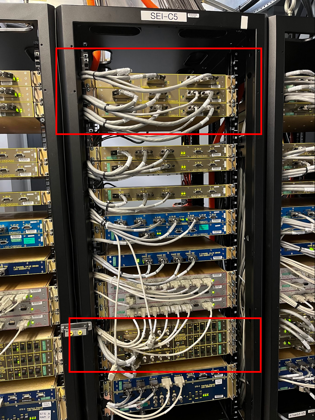
Betsy let us know that she's ready to start disconnecting cables of the ISIBS (the ISI supporting the Beam Splitter) in BSC2. As such, we used D0901301 to guide us, we turned off all three corners of the BSC ISI and T240 Interface Chassis in SEI-C5 U40-38 and U21-19 in the CER. The BSC ISI Interface Chassis are for the on-board capacitive position sensors (both stage 1 and stage 2 CPS), "high" frequency inertial sensors (stage 1 L4Cs and stage 2 GS13s), and the T240 Interface Chassis are for the on-board "low" frequency inertial sensors (stage 1 T240s).

All sensors are OFF as of 1:52p PT (2026-04-23 20:52 UTC).
J. Oberling, R. Crouch, J. Warner, B. Weaver, I. Abouelfettouh
This week we surveyed the position of the components that reside in WBSC2: The BS SUS cage (BSS), the ISI optics table (ISI Stage 2), and the 2 ITM Elliptical Baffles.
BS and the SUS Cage
The first picture shows our FARO survey of points on the BS SUS cage, chiefly along the bottom of the main support structure. These were surveyed by holding the FARO SMR against the hole being measured; the PolyWorks software handles the compensation from the center of the SMR to the point being measured. As can be seen, each point is very close in both X and Y axis position, being less than 0.1mm from its nominal location. The Z axis deviations are larger, but the largest of them is just over 0.25 mm, so every point is well within the positioning specifications used during installation and alignment in 2013.
Line 1 in the picture was created from the first and last survey points and represents the pointing of the BS SUS cage; all angles are reported in degrees. Some things to note here: I'm using the Acute Angle datum in PolyWorks, which is the angle measured from the closest axis. For the HR surface normal of the BS, the X Acute Angle is measured from the -X axis, the Y Acute Angle is measured from the +Y axis, and the Z Acute Angle is measured from the +Z axis. Since Line 1 is roughly perpendicular to the surface normal of the BS HR face, the axes the angles measure from are changed: The X Acute angle is now measured from the +X axis, the Y Acute Angle is still from the +Y axis, and the Z Acute Angle is now from the -Z axis. In addition, since Line 1 is nominally perpendicular to the BS HR surface normal I would expect the X and Y Acute angles to be swapped (BS X Acute = Line 1 Y Acute; BS Y Acute = Line 1 X Acute), but they aren't exactly. This appears to be a small error in the CAD model, if we make the assumption that the BS HR surface and the HR side of the BS SUS cage are nominally pointing in the same direction. This does, however, change the deviations for the X and Y Acute angles for Line 1. The table below shows what the data for Line 1 should be:
| Nominal | Measured | Deviation | |
| X Acute Angle | 44.9699 | 44.9073 | -0.0626 |
| Y Acute Angle | 45.0301 | 45.0927 | 0.0626 |
| Z Acute Angle | 90.0000 | 89.9661 | -0.0339 |
This means the BS SUS cage is yawed 0.0626°, or ~1.09 mrad, in the clockwise (CW) direction when looking from the top down (since Line 1 is closer to the +X axis than it should be). The Z Acute Angle represents a slight counterclockwise (CCW) roll of the SUS cage, when looking directly at the HR surface of the BS.
To attempt to better locate the BS in the IFO coordinate system, several measurements were taken with a ruler from points on the "Figure 8" section of the BS SUS cage to the BS optic itself. All measurments except one were done using a scale with 0.5 mm tic marks (so accurate to +/- 0.25 mm). The 10:00 "Figure 8 face to BS HR face" measurement had to be done using the side of the scale in inches, with 1/32" tic marks (so accurate to +/- 1/64") and then converted to mm (so accurate to +/- 0.4 mm). The measurements positions are listed like the BS HR surface is a clock, and assumes you are looking directly at the HR surface. The below table gives those results:
| Outside Edge of Figure 8 to BS optic edge (mm) | Front face of Figure 8 to BS HR face (mm) | |||||
| 3:00 (-X/-Y) | 6:00 (-Z) | 9:00 (+X/+Y) | 2:00 | 6:00 | 10:00 | |
| Measurement | 49.0 | 48.75 | 48.5 | 24.75 | 27.0 | 26.2 |
| CAD Nominal | 49.0 | 49.0 | 49.0 | 26.2 | 26.2 | 26.2 |
| Deviation | 0.0 | -0.25 | -0.5 | -1.45 | +0.8 | 0.0 |
The BS sits decently centered in the Figure 8 portion of the SUS cage, a little bit low and to the +X/+Y side. I would say not as much horizontally as it looks from the table, given the inherent error with reading the scale (the BS is not wider than its 370.0 mm specification, it's actually 0.15 mm narrower at 369.85 mm). The pointing implied by this measurement, however, is more than a little alarming. The 2:00 and 10:00 measurements show a significant yaw of the BS optic w.r.t. the SUS cage, and in the same direction as the yaw of the SUS cage as measured by the FARO. There is ~320.0 mm between the 2:00 and 10:00 positions on the BS, so that 1.45 mm difference in depth is a 4.53 mrad CW yaw. When added to the CW yaw of the SUS cage, this measurement shows that the BS optic is yawed 5.62 mrad CW from its nominal yaw. Even assuming the errors fall in our favor (so the 2:00 at 25.0 mm and the 10:00 at 25.8 mm), that's still a 3.59 mrad CW yaw (2.5 mrad BS and 1.09 mrad SUS cage). In addition, the 6:00 measurement implies a significant downward pitch of potentially several mrad, although with no way to measure the top of the optic we can't actually measure it. I have to be honest, I'm having a very hard time believing this measurement; we will revisit this once the BS cartridge has been moved to the test stand, where we have a better field of view for the FARO, more room to work and much better lighting around the BS, and can take direct measurements of the BS position and pointing using a total station and laser autocollimator (although there is no guarantee that the optic will be pointing in exactly the same direction after being craned across the LVEA). More to come on this.
ISI Optics Table
The second attachment shows the ISI positions as measured by the FARO. I've corrected the Z axis positions for the length of the rod we use to hang the SMR from the ISI so they give a better idea of the Z axis position. Not much can be said here, as LLO discovered that while these rods are good for measuring the Z axis position, they are not at all good at measuring X and Y. This makes sense as they were designed to be accurate in length and only length, so there's no guarantee that X and Y are repeatable. We plan on measuring the X and Y errors of this particular set of rods in the coming days (align to a table with a known hole pattern, attach the rod and measure with the FARO, repeat multiple times to see how the X and Y positions change). For now, we can say that the ISI is lower on the -X side vs the +X side, and lower on the +Y side vs the -Y side. I'm not alarmed by the deviations in Z axis position, as this ISI was supposed to be lower by ~2.5 mm (to place the BS in proper Z axis position, since it's lower in the IFO coordinate system but the SUS is the same length as the QUADs), but this was never captured in the CAD files.
ITM Elliptical Baffles
The final four attachments show our survey of both ITM elliptical baffles. Our view of the baffles and available fiducials to take measurements from were both limited, but we can say a few things.
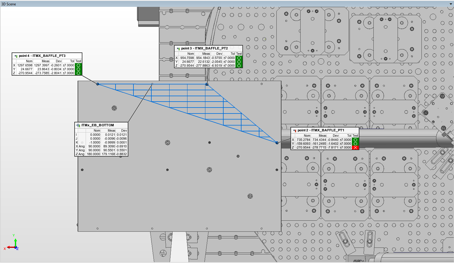
ITMx Elliptical Baffle
We were able to get two points along the +Y bottom edge of the baffle, a single point along the +Y top edge, and single point near the center of the -X bottom edge of the baffle. From this I made a couple of planes that represent the +Y and bottom sides of the baffle and are shown in the third and fourth attachments; I, J, and K are the direction cosines of the surface normal of the plane, while the listed angles are the angle from the surface normal to the +X, +Y, and +Z axes. Interestingly, the point on the top edge looks very well aligned, within 1.0 mm all around, while the points along the bottom of the baffle are all low by several mm. In addition, there appears to be a significant upward pitch to the baffle. Jim did note that when attaching the transport bracket he had to push the baffle in the +X direction to clear ~0.5 mm at the point where the bracket attaches to the suspended portion of the baffle. This point is roughly 476 mm away from the baffle's suspension blade, so this is an ~1.05 mrad angle. Applying this same angle along the bottom of the baffle box gives an ~ -0.33 mm Z axis move of that bottom -X edge of the baffle, so this does not account for the measured deviation. In addition to the pitch, the bottom plane also shows a large roll (CCW when looking at the ITMx in WBSC3), while the side plane shows a large yaw (CCW when looking from the top down). We know these baffle panels aren't exactly straight, so it's hard to say if this significant pointing is also present on the elliptical hole of the baffle (we couldn't see it, so we couldn't measure it directly).
ITMy Elliptical Baffle
Similar to the ITMx baffle, we were only able to get a handful of points along the -X side and the bottom of the baffle. I made planes from these points representing the -X side and the bottom of the baffle (fifth and sixth attachments). As seen with the ITMx baffle, the points along the top of the baffle all look good while the points on the bottom are too low by several mm. There is a significant upward pitch to this baffle as well, as well as a large roll (CCW when looking at ITMy in WBSC1) and yaw (CCW when looking from the top down), although none are as large those as seen on the ITMx elliptical baffle. Again, we could not see the elliptical hole in the baffle to measure it, so we can't say if this pointing is an artifact of the panels or also present on the actual baffle portion of the baffle.
This completes our in-chamber measurements of the WBSC2 cartridge assembly, and closes LHO WP 13171.
I also want to note, Ryan and I also preformed some in-chamber FARO measurements in WHAM3 (ISI, MC2 SUS cage, PR2 SUS cage, MC2 and PR2 baffles) on April 10th; I will post those as soon as I get a chance to process the data in PolyWorks.




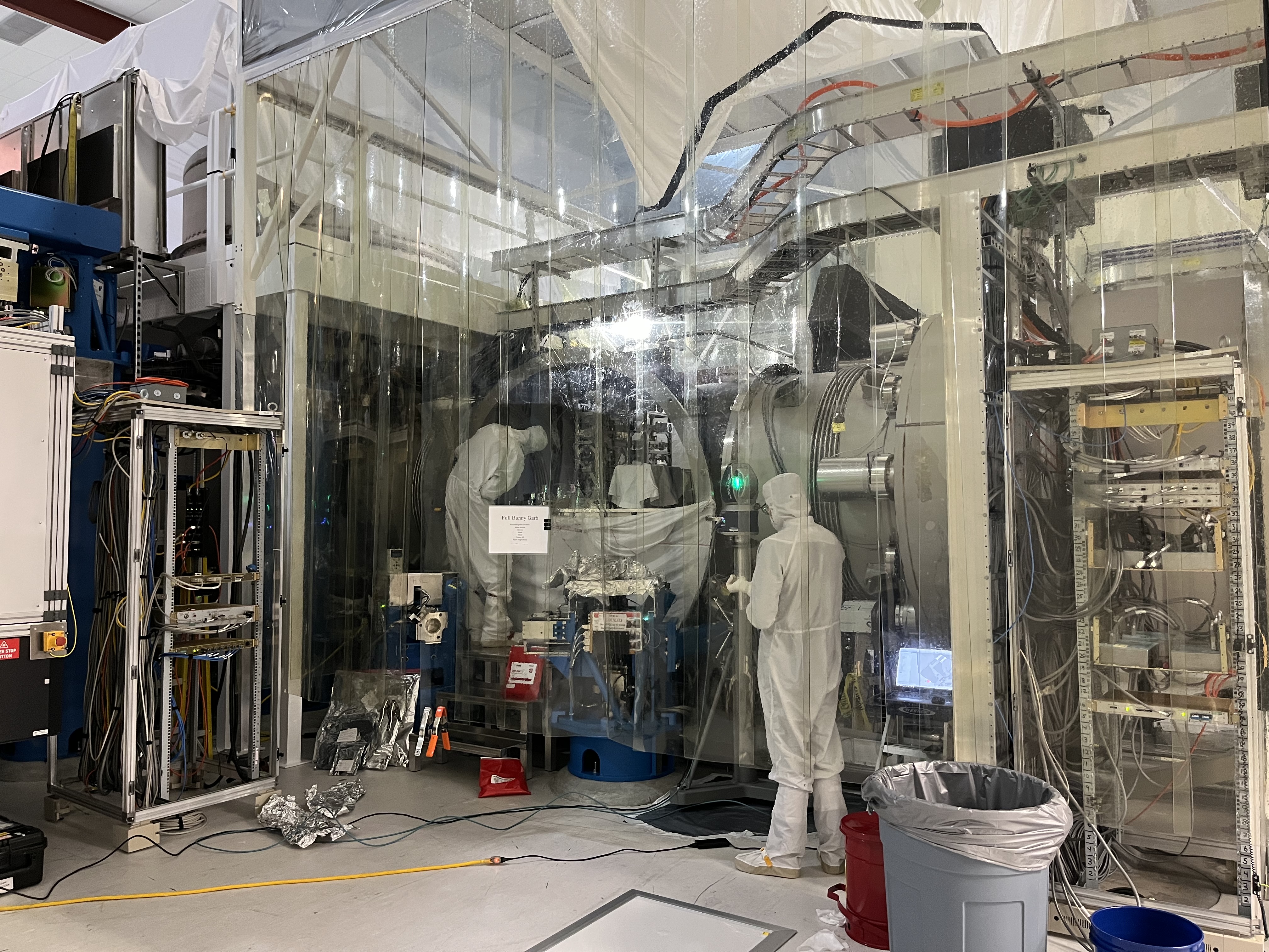
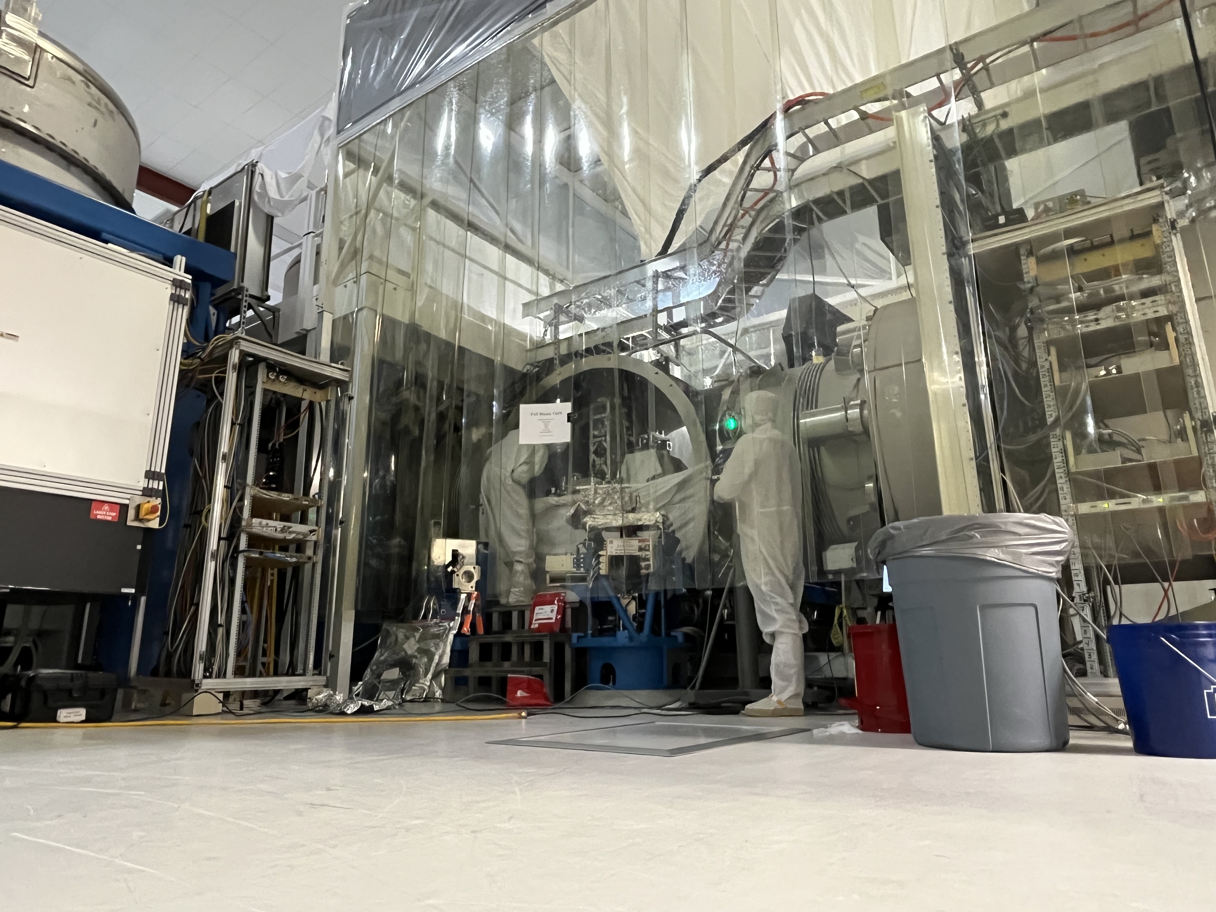
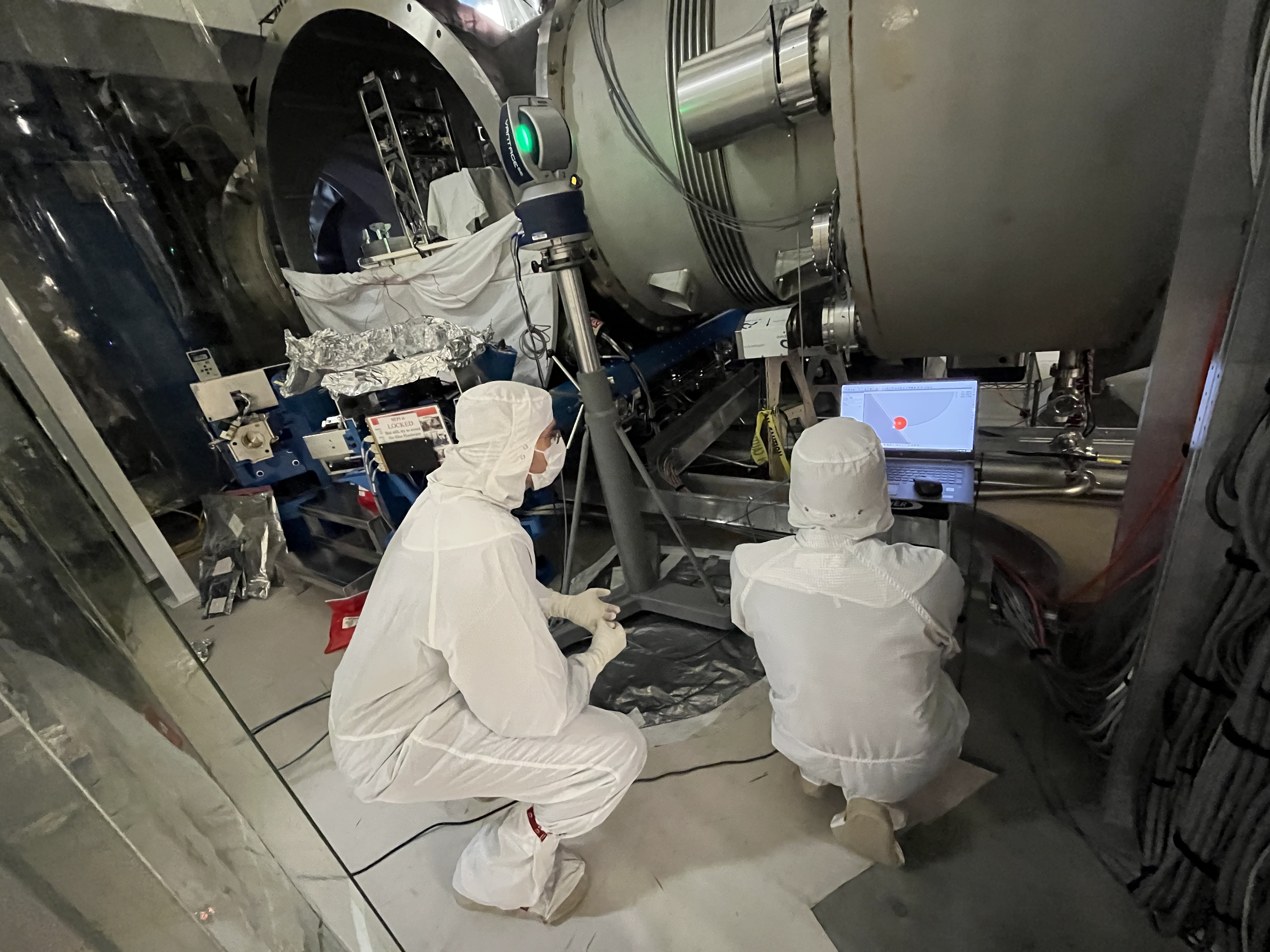
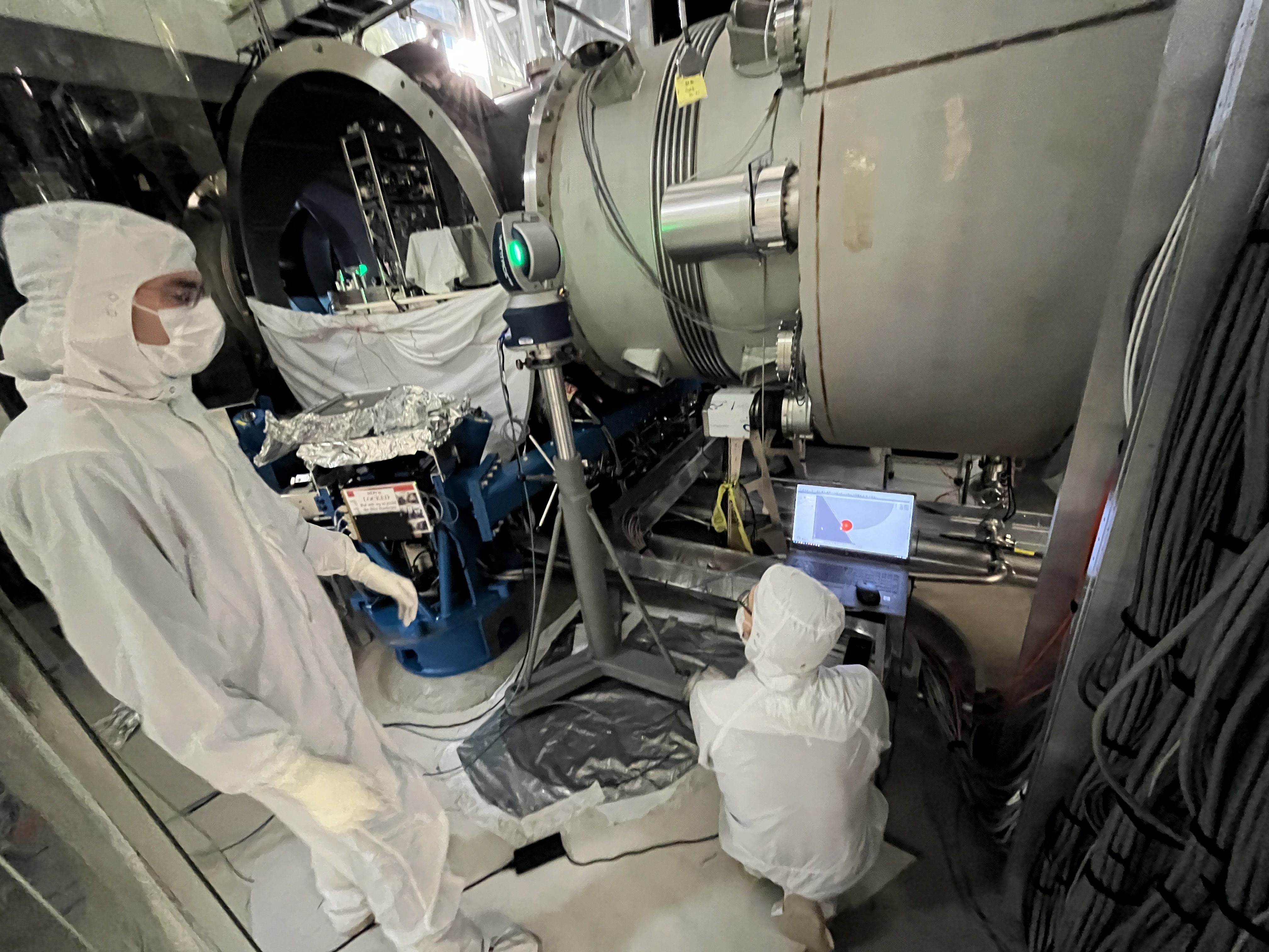
Some action photos while Jason & RyanC were chamberside at HAM3.

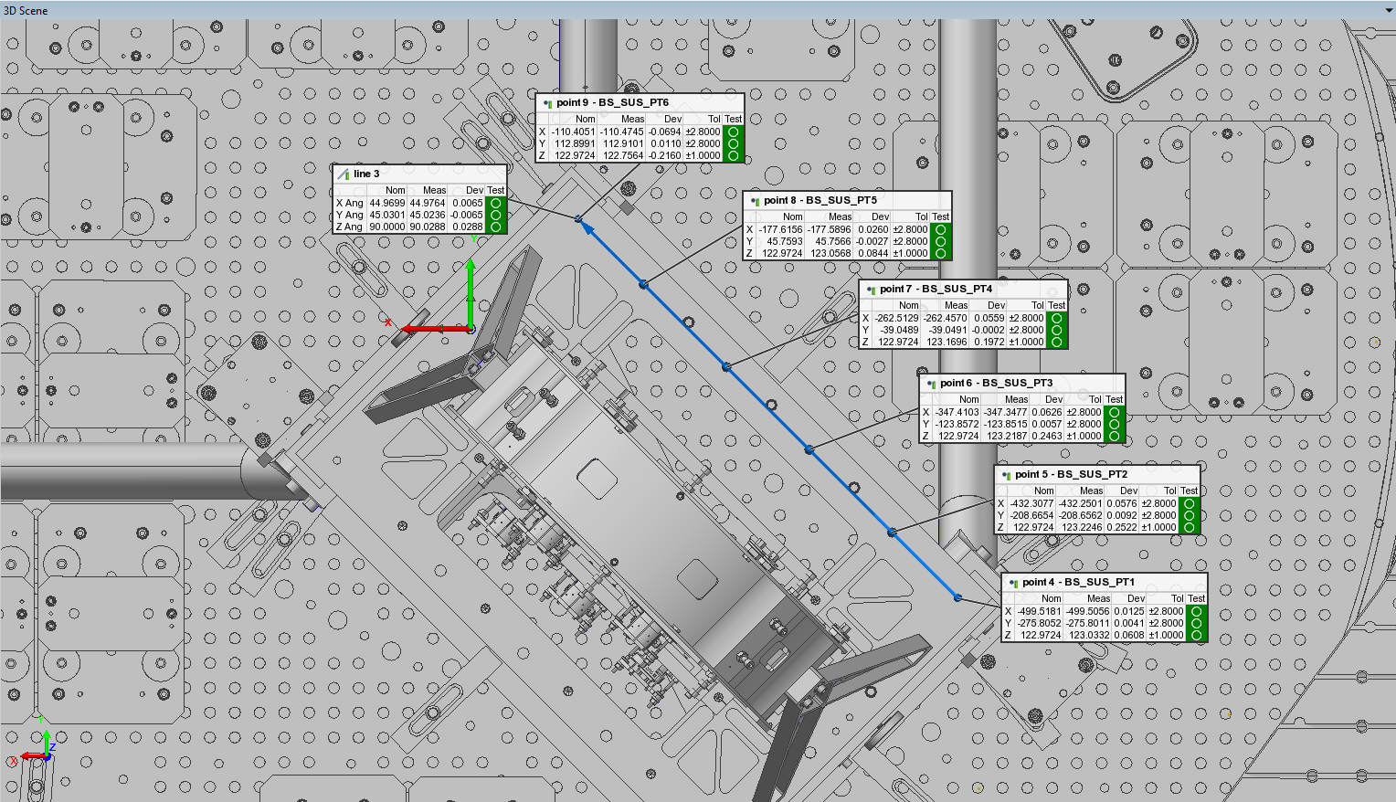
Ignore the very first table in the above alog, concerning the yaw of the BS SUS cage, as I apparently forgot how to do math when creating that. In writing a master alog trying to tie together the series of measurements we took on the BS (still a WIP) I went back to PolyWorks and, in a separate file so to not compromise the existing data, rotated the CAD model so the HR face of the BS SUS matched the target yaw of the BS HR surface. The results of that are shown in the attachment here. The angles listed for Line 3 are measured from the positive axis; i.e. X Ang is measured from the +X axis. Takeaways:
Honestly, ignore everything I wrote above about BS yaw. Not only was my math bad on the rotation correction (see previous comment), the error bar on the scale measurements used to calculate the yaw is so large that the only thing we can definitively say about the BS in-chamber yaw is that it is yawed CW w.r.t. the SUS cage.
As explained above, we did 2 measurements of the BS optic distance from the front face of the HR side Figure 8, one at roughly the 10 o'clock position and one at roughly the 2 o'clock position. The only Class B ruler we had at the time had mm on one side and inches on the other; the mm side had 0.5 mm tic marks for a +/- 0.25 mm error bar, while the inches side had 1/64" tic marks for an error bar of +/- 0.4 mm. 2 measurements were required at each position, one from the HR Figure 8 to the gold wire baffle and then one from wire baffle to the BS itself. Carrying the error bars from the multiple ruler measurements all the way through the yaw calculation yields a yaw of 4.53 +/- 4.06 mrad CW. With the error bar almost as large as the result, the only definitive thing we can say is that the BS optic was yawed w.r.t. the SUS cage, but we can't put an accurate number on it with the measurement method used.
Last checked in alog 89599.
All trends look consistent and/or similar with last month's with the exception of the EX pump, which Jim commented on last time. This pump was seen going up in pressure. This pressure has since remained stable.
WP 13154
a-Plus O5 SUS HAM5 (sush5) System Wiring Diagrams - D2300380
aLIGO SUS HAM 5-6 System Wiring Diagrams - D1002740
SUS-C7/ SUS-C8
Two HAM-A coil drivers were installed in the SUS-C7 rack, part of LO3. We decided to use the existing OMC cables for the new OFI. Cables are going to correct CER and field rack. OMC is being moved to the MER. Once HAM6 is vented the OM1/OM2/OM3 electronics and cabling will be removed.
SEI-C1
Started clean-up of the SEI racks. Removed a HAM ISI Interface Chassis from SEI-C1. This was part of the HAM1 L4C testing back in 2018. Plan is to remove the STS distribution electronics. See alog 89835 for testing of sending signals over IPC.
ISC-C3
The Heliax cable for SPI was landed in ISC-C3 (Patch Panel U37/U38, port 4)
LVEA Work
Finished routing the ±18V power cable for CHETA Y around BSC8 and BSC1. Cable was landed in the TCS-R2 rack. We spent some time cleaning cabling in the TCS rack and the space between the TCSY enclosure and BSC1.
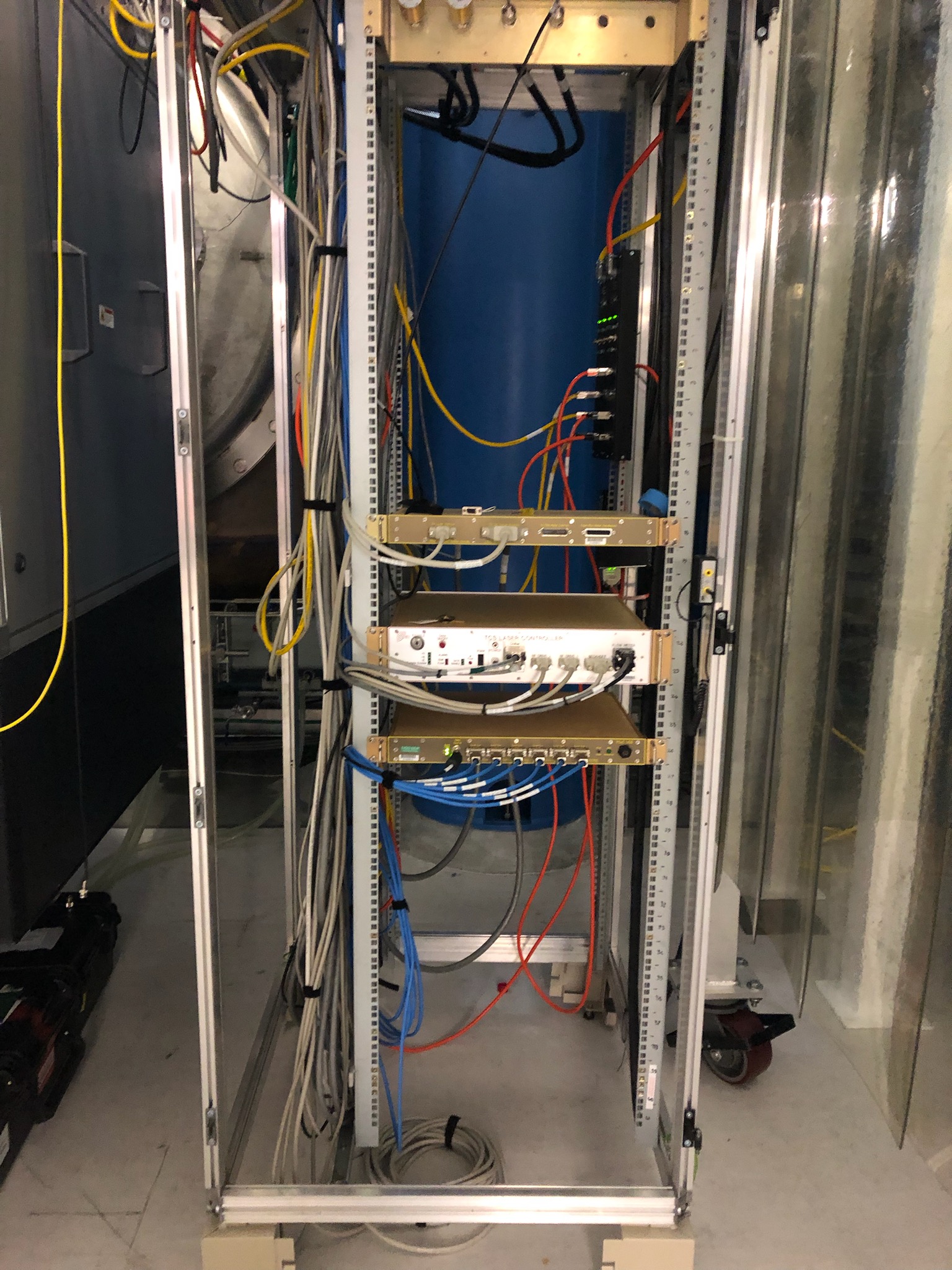
F. Clara, C. Gray
Monthly FAMIS Check (#39345)
T240 Centering Script Output:
Averaging Mass Centering channels for 10 [sec] ...
2026-04-06 09:03:52.267253
There are 11 T240 proof masses out of range ( > 0.3 [V] )!
ETMX T240 2 DOF X/U = -1.862 [V]
ETMX T240 2 DOF Y/V = -1.903 [V]
ETMX T240 2 DOF Z/W = -1.191 [V]
ITMX T240 1 DOF X/U = -2.423 [V]
ITMX T240 1 DOF Z/W = 0.37 [V]
ITMX T240 3 DOF X/U = -2.723 [V]
ITMY T240 3 DOF X/U = -1.215 [V]
ITMY T240 3 DOF Z/W = -3.11 [V]
BS T240 3 DOF X/U = -0.38 [V]
HAM8 1 DOF Y/V = -0.456 [V]
HAM8 1 DOF Z/W = -0.766 [V]
All other proof masses are within range ( < 0.3 [V] ):
ETMX T240 1 DOF X/U = -0.079 [V]
ETMX T240 1 DOF Y/V = -0.076 [V]
ETMX T240 1 DOF Z/W = -0.114 [V]
ETMX T240 3 DOF X/U = -0.097 [V]
ETMX T240 3 DOF Y/V = -0.159 [V]
ETMX T240 3 DOF Z/W = -0.087 [V]
ETMY T240 1 DOF X/U = 0.027 [V]
ETMY T240 1 DOF Y/V = 0.07 [V]
ETMY T240 1 DOF Z/W = 0.259 [V]
ETMY T240 2 DOF X/U = -0.204 [V]
ETMY T240 2 DOF Y/V = 0.238 [V]
ETMY T240 2 DOF Z/W = 0.042 [V]
ETMY T240 3 DOF X/U = 0.267 [V]
ETMY T240 3 DOF Y/V = 0.048 [V]
ETMY T240 3 DOF Z/W = 0.007 [V]
ITMX T240 1 DOF Y/V = 0.28 [V]
ITMX T240 2 DOF X/U = 0.119 [V]
ITMX T240 2 DOF Y/V = 0.163 [V]
ITMX T240 2 DOF Z/W = 0.263 [V]
ITMX T240 3 DOF Y/V = 0.143 [V]
ITMX T240 3 DOF Z/W = 0.057 [V]
ITMY T240 1 DOF X/U = -0.045 [V]
ITMY T240 1 DOF Y/V = 0.16 [V]
ITMY T240 1 DOF Z/W = -0.038 [V]
ITMY T240 2 DOF X/U = 0.052 [V]
ITMY T240 2 DOF Y/V = 0.2 [V]
ITMY T240 2 DOF Z/W = 0.036 [V]
ITMY T240 3 DOF Y/V = -0.021 [V]
BS T240 1 DOF X/U = 0.043 [V]
BS T240 1 DOF Y/V = -0.119 [V]
BS T240 1 DOF Z/W = -0.038 [V]
BS T240 2 DOF X/U = 0.235 [V]
BS T240 2 DOF Y/V = -0.134 [V]
BS T240 2 DOF Z/W = 0.132 [V]
BS T240 3 DOF Y/V = -0.158 [V]
BS T240 3 DOF Z/W = -0.169 [V]
HAM8 1 DOF X/U = -0.297 [V]
Assessment complete.
STS Centering Script Output:
Averaging Mass Centering channels for 10 [sec] ...
2026-04-06 09:04:04.266410
There are 2 STS proof masses out of range ( > 2.0 [V] )!
STS EY DOF X/U = -4.57 [V]
STS EY DOF Z/W = 2.369 [V]
All other proof masses are within range ( < 2.0 [V] ):
STS A DOF X/U = -0.496 [V]
STS A DOF Y/V = -0.768 [V]
STS A DOF Z/W = -0.628 [V]
STS B DOF X/U = 0.152 [V]
STS B DOF Y/V = 0.942 [V]
STS B DOF Z/W = -0.444 [V]
STS C DOF X/U = -0.995 [V]
STS C DOF Y/V = 0.908 [V]
STS C DOF Z/W = 0.636 [V]
STS EX DOF X/U = 0.606 [V]
STS EX DOF Y/V = -0.511 [V]
STS EX DOF Z/W = -0.372 [V]
STS EY DOF Y/V = 1.135 [V]
STS FC DOF X/U = 0.153 [V]
STS FC DOF Y/V = -1.192 [V]
STS FC DOF Z/W = 0.629 [V]
Assessment complete.
FAMIS Link: 39345
Only CPS channels which look higher at high frequencies (see attached) would be the following:
In the bash window got ZERO notes.
J. Kissel

More experience with the SPI in the optics lab yields an explicit ADC / DAC channel usage list for the SPI pathfinder. I've uploaded it as a part of G2401479-v2, but attached here for convenience. This kind of critical info / easy look-up table should be a part of the Altium wiring diagram, D2400111, but sometimes given there saturation of information it's nice to just have a look-up table especially when building front-end models.

Enjoy, future us!
FAMIS Link: 39344
Only CPS channels which look higher at high frequencies (see attached) would be the following:
In the bash window we get this note:
"BSC high freq noise is elevated for these sensor(s)!!!: BSITMy_ST1_CPSINF_H3 "
TITLE: 03/24 Day Shift: 1430-2330 UTC (0730-1630 PST), all times posted in UTC
STATE of H1: Planned Engineering
OUTGOING OPERATOR: None
CURRENT ENVIRONMENT:
SEI_ENV state: CALM
Wind: 14mph Gusts, 10mph 3min avg
Primary useism: 0.03 μm/s
Secondary useism: 0.19 μm/s
QUICK SUMMARY:
Arrived to see lots of tripped Watchdogs. This was due to a M7.5 Tonga earthquake from last night just before 10pm local time (5utc). Dave contacted me to give me the heads up on this and noted that ITMy actually had the Hardware Watchdog trip---this requires someone to go out to the CER to push a button to restore coil drivers. We were hesitant on addressing this without Jim's guidance--not sure how powering things back on would affect the system. Will message Jim with a heads up for BSC1's ITMy/BSC1-ISI/BSC1-HEPI. Will continue bringing everything else back.
Other than that, today is Maintenance Day. The Filter Cavity Tube has light flashing and so its small gate valves must still be open (I had thought the discussion was to close these gate valves to allow craning over the FC Tube, but not certain on this.
Day1 of 2-day CEBEX workshop begins today.
Earthquake Recovery Status:
ITMy Hardware Watchdog continues to be looked at with Fil/Jonathan
UPDATE: Fil was able to restore the ITMy watchdog (he held the RESET for a few seconds and waited for the lights to change on the front panel). ITMy HEPI/ISI are redamping/isolating.
Hepi Pump Trends (Monthly) Famis 39954:
On Jan 26th the HPI-PUMP_EX_PRESS1_PSI started rising in maximum pressure. and on maybe feb 2nd it started getting worse. Seems like it has plateau-ed on Feb 16th, but the Pressure still remains elevated.
That channel back in Oct was between 92.4-92.6 PSI.
And now it's between 91.9 - 93.5 PSI. I'm not sure if this is out of bounds for HEPI.

I have looked at the EX pressures a bit and I suspect that one of the pressure sensors on the EX manifold has gone bad.
On the attached trend, the top 2 traces are PRESS1 and PRESS2, bottom 2 traces are the same pressures at EY. EX PRESS1 starts seeing bigger peak to peak signal starting about 50 days ago, but PRESS2 doesn't see this increase in pressure noise. Second attach image is a zoomed in trend of the same channels. EX PRESS1 seems to have some kind of 1hz oscillation. PRESS2 might be seeing some of this same signal, but not to the same extent. The supply pressure to the VEA at EX definitely doesn't see this 1hz signal, so I think it's either not real or it's being filtered out at the manifold.
I have yet to go down to EX and test this, but I will try to do so this week.


FRS ticket: https://services1.ligo-la.caltech.edu/FRS/show_bug.cgi?id=37356
Only CPS channels which look higher by eye at high frequencies (see attached) would be the following:
The following work was completed today:
Remaining work on SUS-R2 includes installation of power junction box, power sequencer, and a ±18V power strip.
F. Clara, J. Figueroa, M. Pirello and R. Thompson

