REMOVE SEARCH FILTER
SEARCH AGAIN
Search criteria
Section: H1
Task: IOO
This is a belated alog from Tuesday.
Starting point: Same alignment for MC123, IM123 as last Friday, i.e. the IM4 baffle NOT centered nor unclipped.
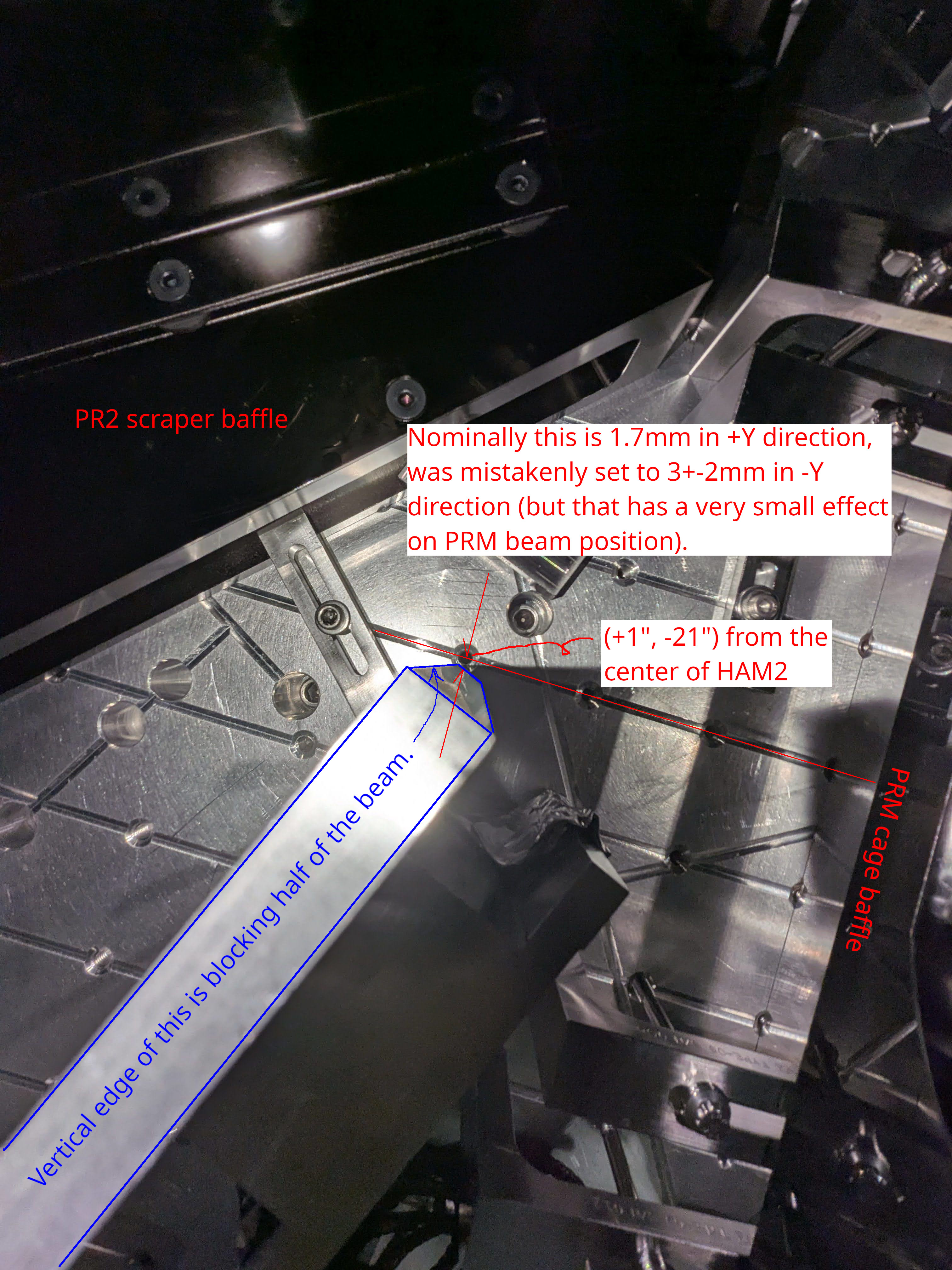
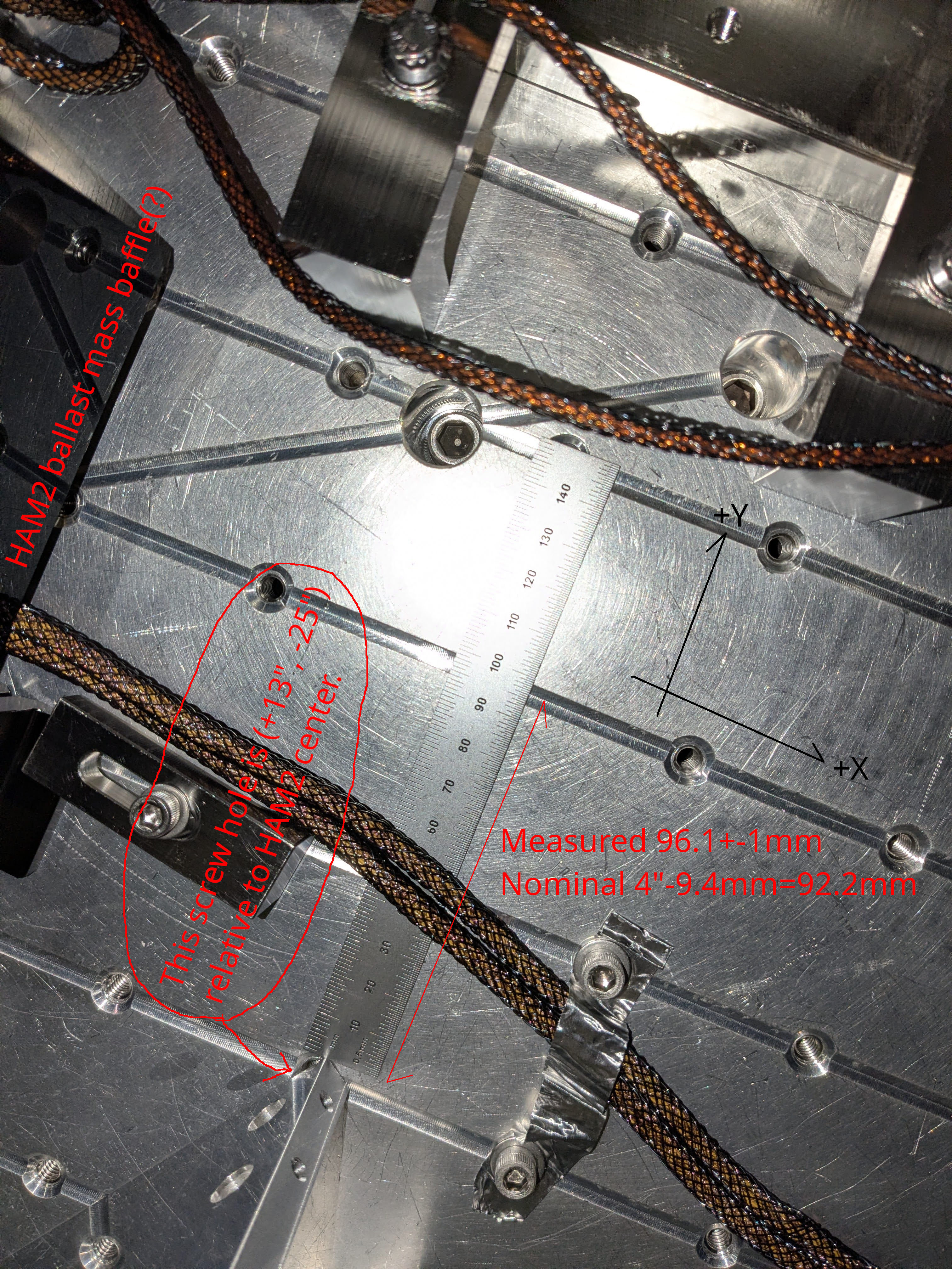
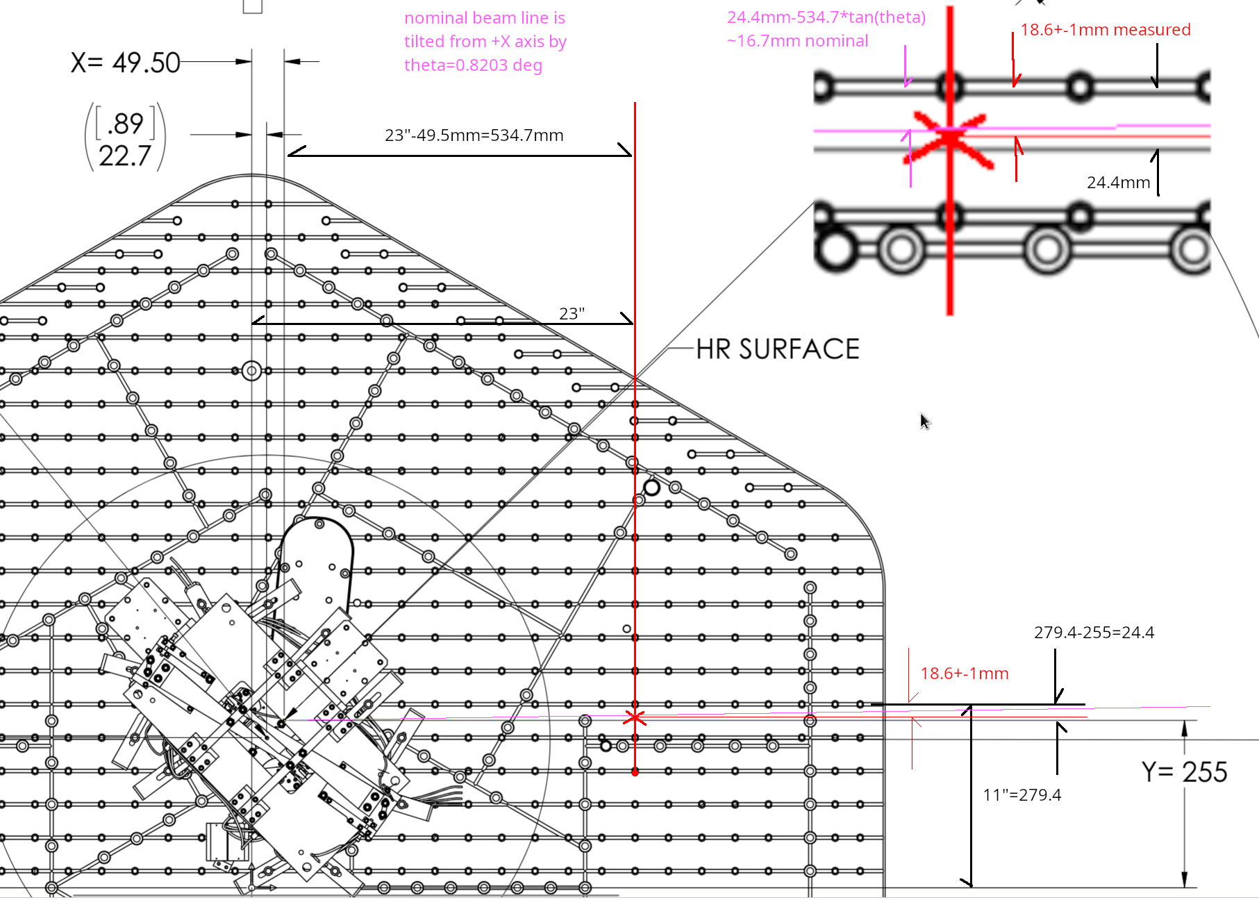
Without touching IMC and IM1/2/3, we rotated IM4 to steer the beam close enough to the nominal beam position in front of PR2, and measured the beam position horizontally and vertically relative to the known screw hole in front of PR2 and PRM.
The distance between IM4-PRM beam line as of now relative to the nominal PRM-PR2 center line was calculated to be 3.9+-1.1mm in -Y direction and too low by 2.9+-1.1mm. See measurement_cartoon.jpg for the horizontal position case. Height is derived in the same way. Since the beam position in front of PR2 is not grossly off, and since IM4 is much, much closer to PRM than PR2, you can use these numbers as the spot position on PRM, too.
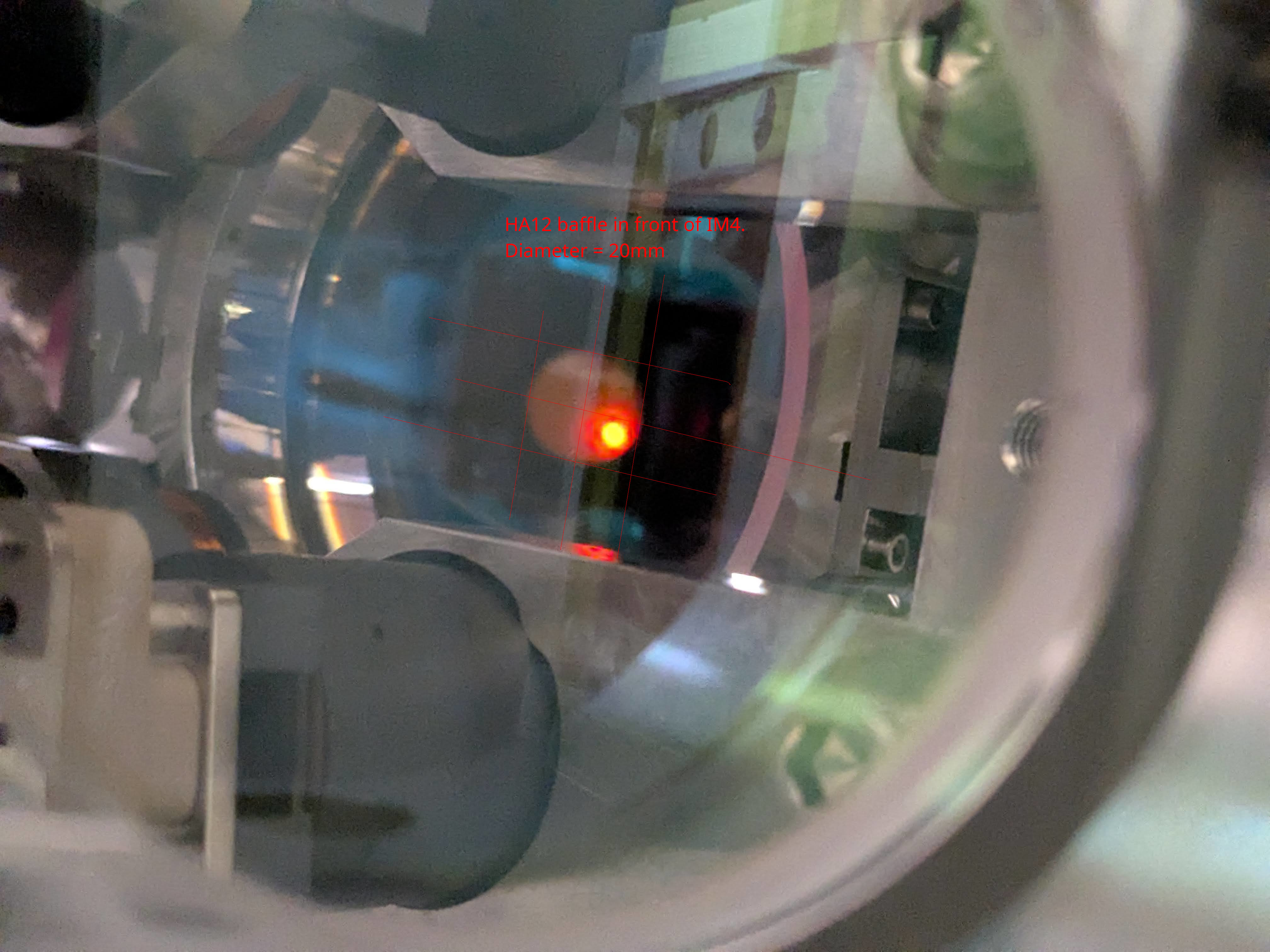
From IM4baffle_20260526.jpg, centering the beam on PRM will correct the height on IM4 baffle (HA12). Horizontally it will within a couple mm or so from the center.
As we're running out of time, give up the idea to understand what happened to the alignment during the vent before closing HAM2. We should recenter things whenever possible (but only when the IFO REFL path and POP sled path are not disturbed to the point we clip or lose the beam).
following is the table of slider offsets as of now.
| IM1 | IM2 | IM3 | IM4 | |
| PIT | 517 | 810 | -614 | 531 |
| YAW | -387 | -88 | 385 | 64 |
Even though the physical PIT angle of the optics relative to the local vertical axis is arbitrary, it seems that IM1 is bringing the beam down on IM2, IM2 is bringing down the beam further on IM3, and IM3 is bringing up the beam on IM4 and PRM. But IM2 is twise as efficient as IM3 for changing the beam position on PRM. Besides, the beam is already coming down from MC2 to MC3 (about 10mm height difference over 16m, or about 220urad) and I don't know if it makes sense to use IM2 to bring the beam further down. It's worth redistributing PIT as well as YAW offsets to relieve big offsets.
However, note that ultimately IM1-IM2 line defines the IFO REFL path when PRM retroreflects. (Even if you rotate IM2, as far as IM1-IM2 line doesn't change the IFO refl beam won't move.) I won't touch IM1 as moving the beam on e.g. IM2 even just a few mm using IM1 (i.e. a few mm over ~1.8m leverarm) will result in a much bigger change for REFL path in HAM1, potentially risking yet another clipping or maybe the loss of the REFL beam. IMC alignment noted above will change the IM1-IM2 line, but that's basically the angle change of ~3.6mm/16m (i.e. an order of magnitude smaller than when moving IM1 to steer the beam on IM2 in a meangful amplitude). That's small enough it's hard to imagine that the beam will be clipped by IFO refl baffle nor the downstream optics.
So,
|
PIT |
IM2 | IM3 | IM4 | PRM |
| IM2 (810 -> 310, negative 500urad) | 0 | 1.2 | +2.8 | +3.5mm |
| IM3 (-614.7 -> -434.7, positive 180urad) | -0.4 | -0.6mm | ||
| Total change | 1.2 | 2.4 | 2.9mm (higher) | |
| Position as of now | -2.9mm (too low) |
| YAW | IM2 | IM3 | IM4 | PRM |
| From MC2 beam spot change |
0.4mm (-X) |
0.6mm (-X) | 1mm (-X) | 1.2mm (+Y) |
| IM2 (-88 -> 112urad, positive 200urad change) | 0.5mm (-X) | 1.1mm (-X) | 1.4mm (+Y) | |
| IM3 (385urad -> 0, negative 385 urad change) | 0.9mm (-X) | 1.3mm (+Y) | ||
| Total change | 0.4mm (-X) | 1.1mm (-X) | 3mm (-X) | 3.9mm (+Y) |
| Position as of now | 3.9mm (-Y) |
Of course this is assuming that the slider calibration is correct, so take this as a qualitative reference to get the sense of sign of angle changes. Anyway, when this is done, the DAC counts for IM2 and IM3 will be smaller while the beam height on PR2 will be fine.
| IM1 (no touch) | IM2 | IM3 | IM4 | |
| PIT | 517 | 810-> 310 | -614-> -434.7 | 531-> ? |
| YAW | -387 | -88-> 112 | 385-> 0 | 64-> ? |
If centering HA12 (IM4) baffle is important, relocate HA12. I'll ask Rodica.
Make sure that PRM retroreflects. Readjust if not. Check IFO REFL beam on IFO REFL baffle, LSC REFL and ASC REFL sensors.
Recenter IM4_TRANCE by pico.
Realign ISS array (simply because it's easier to do it in air than in vacuum).
Think about POP sled path. Is it conceivable that we'll somehow miss the beam there because we change the beam spot position on PRM?

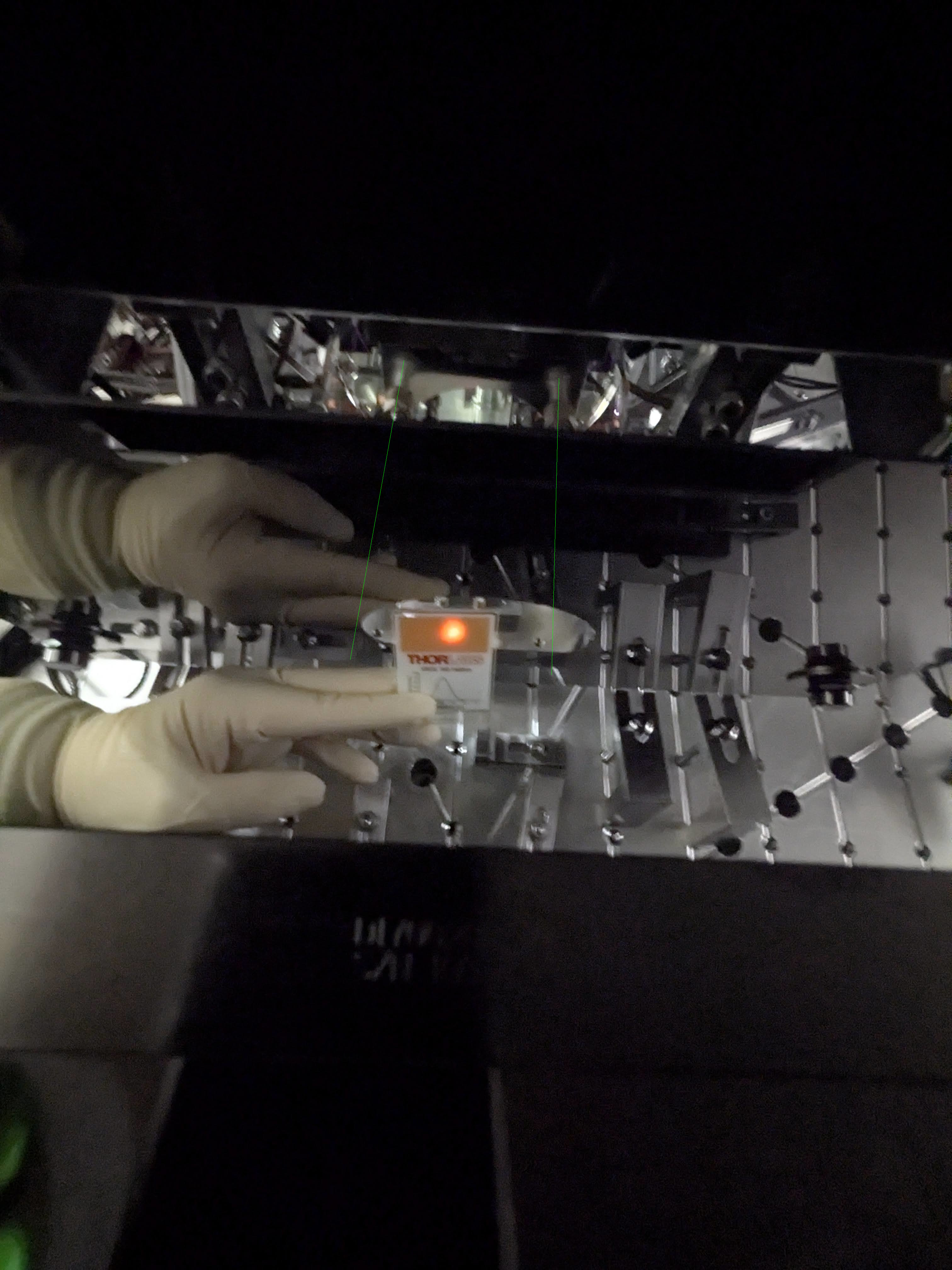
These pictures explain the horizontal beam position measurement in detail.
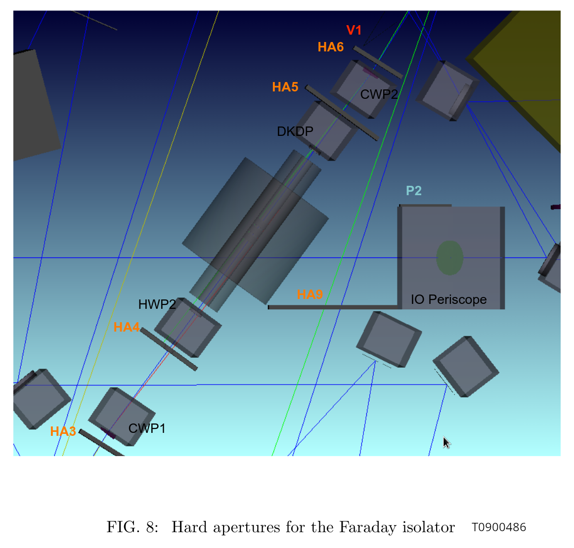
(I learned from T0900486 "IO Stray Light Analysis and Baffle Design" that the IFI input baffle is called HA3, IFI output baffle is HA6, the baffle right in front of IM4 is actually supposed to be a pair of HA12-a and HA12-b but there's only one baffle which I suppose is HA12-a, two-hole baffle for ISS array is HA11, and the last IFO REFL before the beam leaves HAM2 is HA13.)
The beam spot on this baffle was OK before we did anything to IM1 on Tuesday (IFIinput_before.jpg). It's low and toward +X, but nowhere near clipping.
This baffle is right in front of the calcite wedge that deflects the IFO REFL beam away from the incoming beam path from IM2 (HA3_calcite_wedge.png). The lever arm from the wedge to the baffle looks to be an inch or so at most. Hard to imagine that the REFL is clipped while forward going beam is not, but the scattering goes away when I block the beam between PRM and IM4.
The reported "IFO REFL beam clipping" on this baffle is either because the PRM is not retroreflecting, or maybe it's some kind of ghost beam produced from the PRM reflection somewhere.
If we establish that the main IFO refl is NOT clipped when PRM retroreflects, we don't have to worry about this baffle too much (though ghost beam is still a problem).
We will have to bring a card with a hole to make sure that the beam is retroreflected as good as we can.
FYI, IFIinput_aftercentering.jpg shows the same baffle after we made a huge change in IM1.
We don't have any good view of that baffle so it's hard to assess, and we forgot to check it before making changes to IM123.
However, given how small the change was on IFI input baffle, we don't expect that it was very bad before. We'll have to revisit and confirm.
As of now, the measured beam position in front of MC mirrors are as follows this. For measurement points, see mc_beampos_measurement_cartoon.jpg. The height is pretty good for all. MC3 is great horizontally too. Beam spot on MC2 and MC1 are both shifted in -Y direction. MC2 by 3.6+-1mm, MC1 by a couple +-1mm.
| Height from ISI measured [nominal] | Horizontal shift in Y direction from the nominal beam position | |
| MC1 | 154.3 +- 1.3 [155.5] | -1.9 +- 1 |
| MC2 | 167 [166.7] | -3.6 +- 1 |
| MC3 | 154 +- 0.5 [155.5] | +0.3 +- 1 |
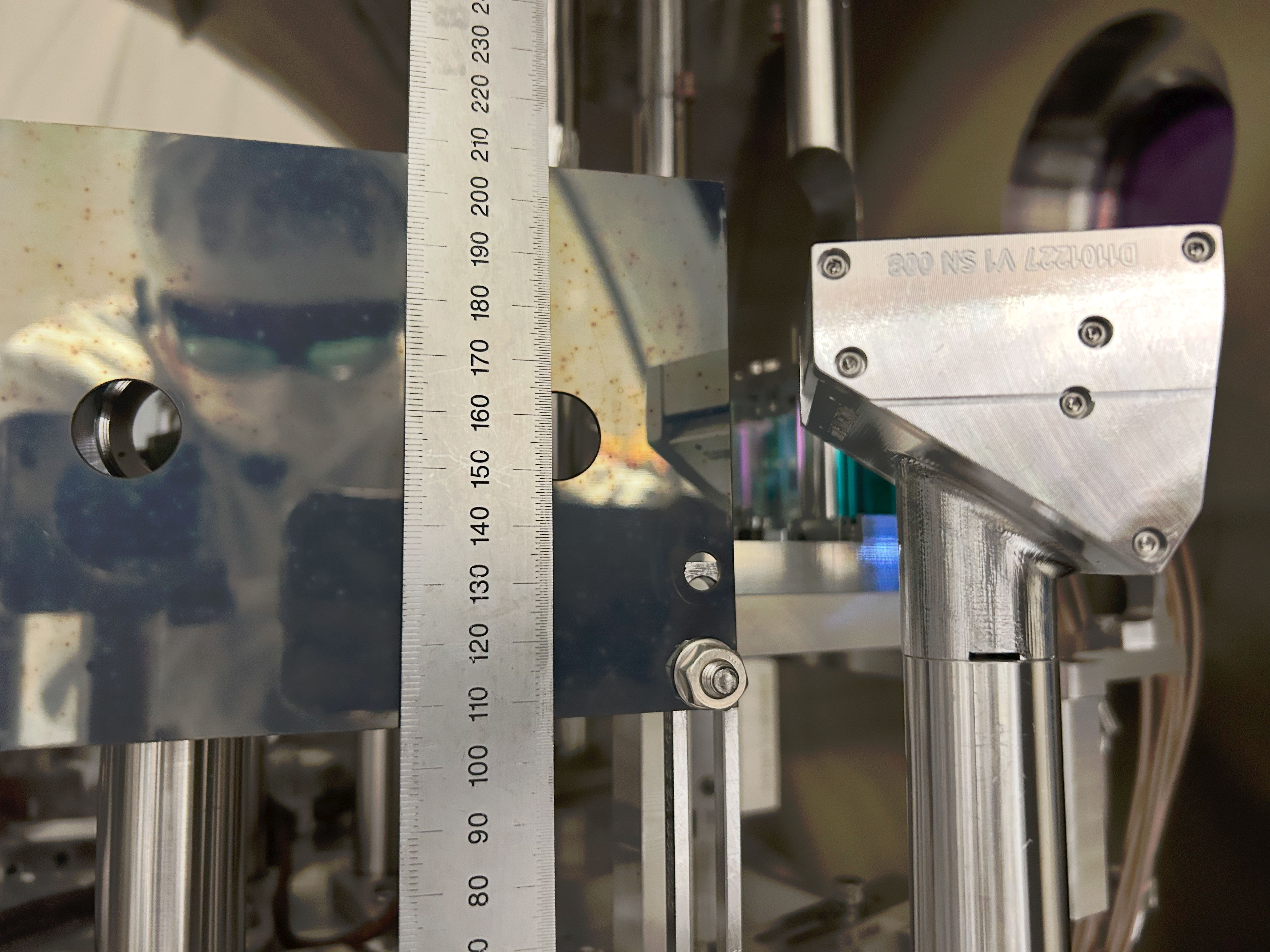
Horizontal positions were determined by covering half of the beam with a vertical hard edge (ruler etc.) and then measuring the position of the edge relative to the neighborhood screw holes using a small ruler, and then using the drawings (D0901088, D901089, D0901099) as well as other IO documents (e.g. T0900486) to figure out the nominal beam location. As an example of tedious work done, see ham2mc1.png. Due to the way it was done, we cannot determine the horizontal position of the beam much better than maybe 1/2 of the beam radius. I just put +-1mm error for all measurements. Height numbers were measured off of a ruler, the error bar (if any) is the difference between Rahul's reading and mine divided by two.
What if we move MC2 or MC3 beam spots (or both) to unclip IM4 baffle (HA12)
To get more sense of magnitude of IMC motion relative to the beam motion on IM4, I calculated how much the IMC alignment should be changed to move the beam on IM4 by 3mm in -Y direction (comfortably far from clipping but not enough to center) without moving IMs.
There are many linear combinations of the MC3 spot position and the angle of the beam coming through MC3 that will move the beam on IM4 by 3mm, so I just chose "parallel transport of MC2-MC3 line" (i.e. no angle change of the angle of the beam coming out of MC3), "rotate MC2-MC3 line around MC3" (i.e. no beam displacement on MC3) and something in-between ("rotate around MC2").
See cartoon_IMC_alignment_to_unclip.png (not to scale but the sign of displacement/rotation is correct along the entire path) and IMC_to_unclip_HA12.png (actual calculation). IMC is not the only thing that moves, we can also move IM2, but anyway. In the "parallel transport" case the beam will be move further away from the center of MC2 (remember it was already 3.6+-1mm in -Y direction to start with so the end result will be 6.8+-1mm in -Y direction). OTOH in the "rotation around MC3" case, the beam on MC2 will move by 11mm in +Y direction so the end result will be 11-3.6+-1=7.4+-1mm in +Y direction.
In all cases the beam will likely still hit the IM4_TRANS because the QPD (Excelitas C30845) has a huge 8mm active diameter, but it will likely be completely in one quadrant. So all of these will be bad solution if we believe that the IM4_TRANS position should be close enough.
Note that the "rotation around MC3" case will result in about 1mrad beam angle change on IM4. This needs to be absorbed by IM4 rotation by about 500urad to send the beam to PR2.
It's also worth noting that IM4-PRM HR distance is almost the same as IM4-IM4_TRANS distance.
What if we fix the beam on IM4_TRANS?
Instead of IMC alignment, now let's think about the beam positions from the end point (IM4_TRANS).
Again, assume that we want to keep the IM4 TRANS beam position. We tried two different IMC alignment, and the beam was clipped on IM4 baffle (HA12) after bringing the beam back to the target IM4 TRANS position.
Moving the beam position on HA12 by 3mm in -X direction without changing the IM4_TRANS position means that we shift the beam position on IM3 by about 8mm. IM3-IM4 path beam angle changes by 4.8mrad counter-clockwise. This is an absolutely huge change.
PRM should be moved by 2.4mrad, and 8mm on IM3 is already the radius of IFI output baffle (HA6) so we'll be worrying about clipping there. There seems to be no solution where the beam is far enough from the IM4 baffle (HA12) edge AND the beam is on the same position on IM4_TRANS as in vacuum.
As far as we assume that IM4_TRANS is trustworthy, it's very likely that the beam was clipping or at least very close to clipping on HA12 in O4.
However, if IM4_TRANS path moved after HAM2 was opened (i.e. somebody bumped something), IM4_TRANS position as of now doesn't mean anything. We have to at least grab and wiggle the steering mirror as well as the QPD for that path to make sure that nothing is loose. (I already did that test for MC2 TRANS, and they didn't move.)
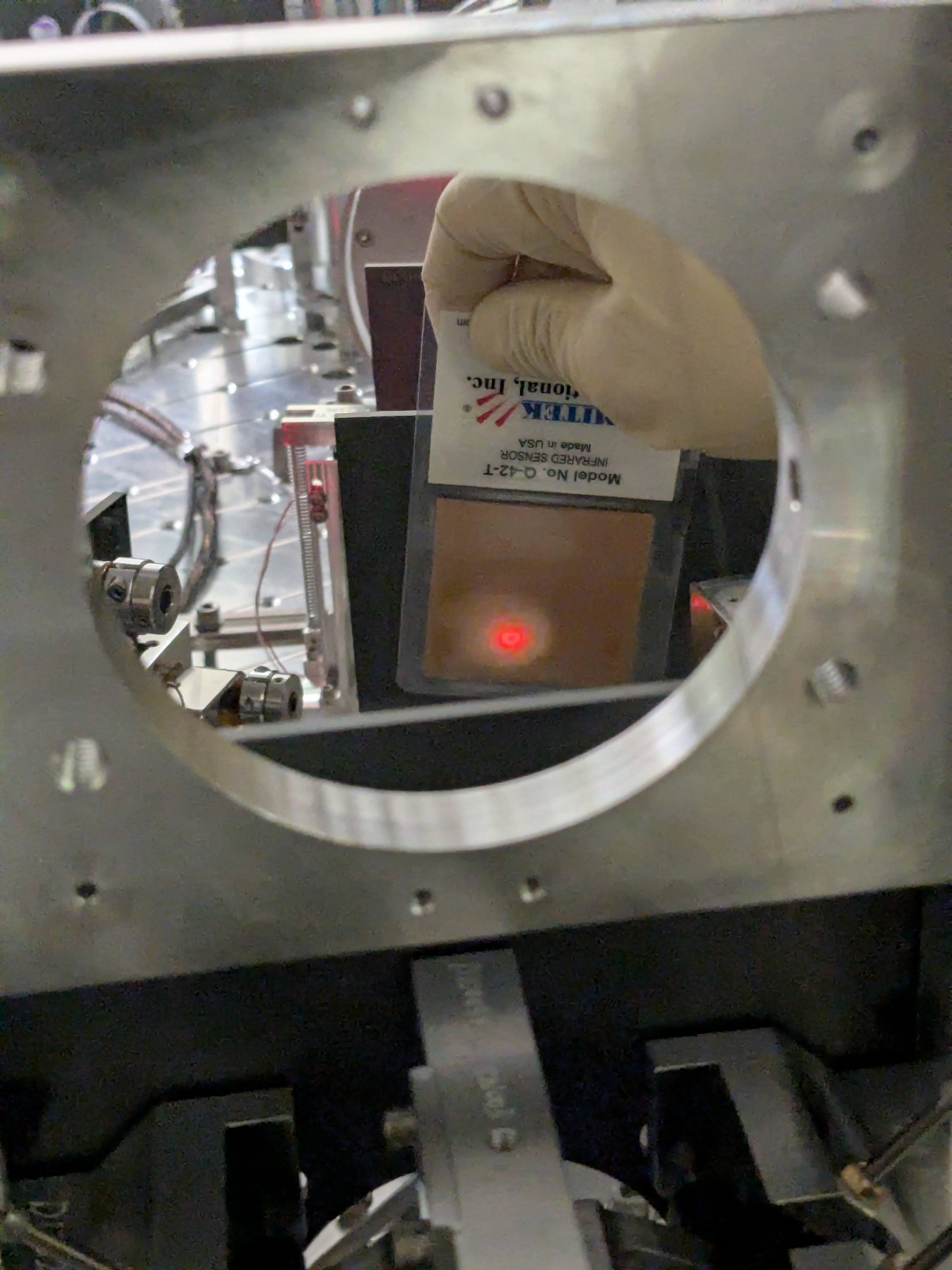
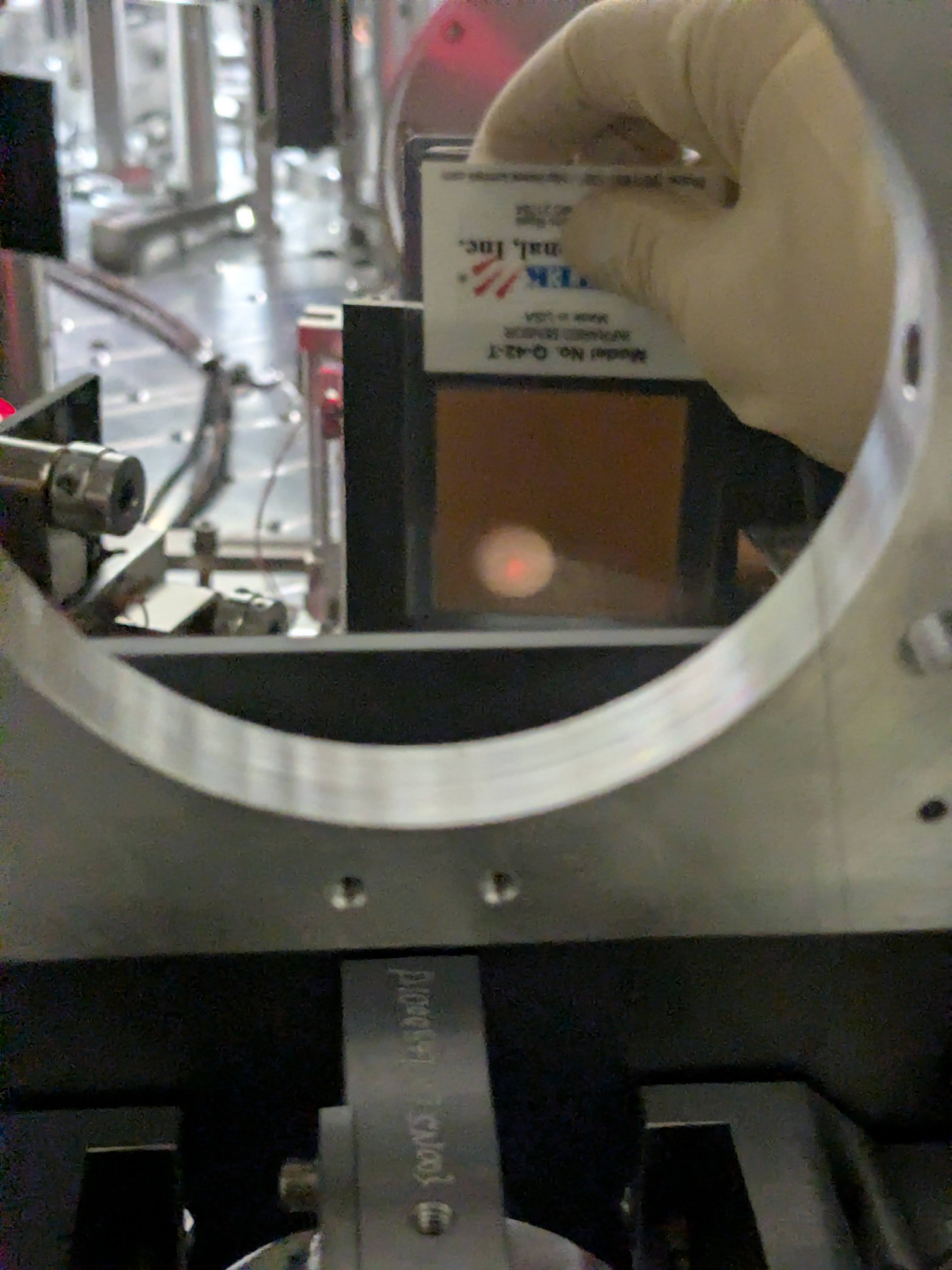


Attached are an example of beam position measurements (in this case MC1).

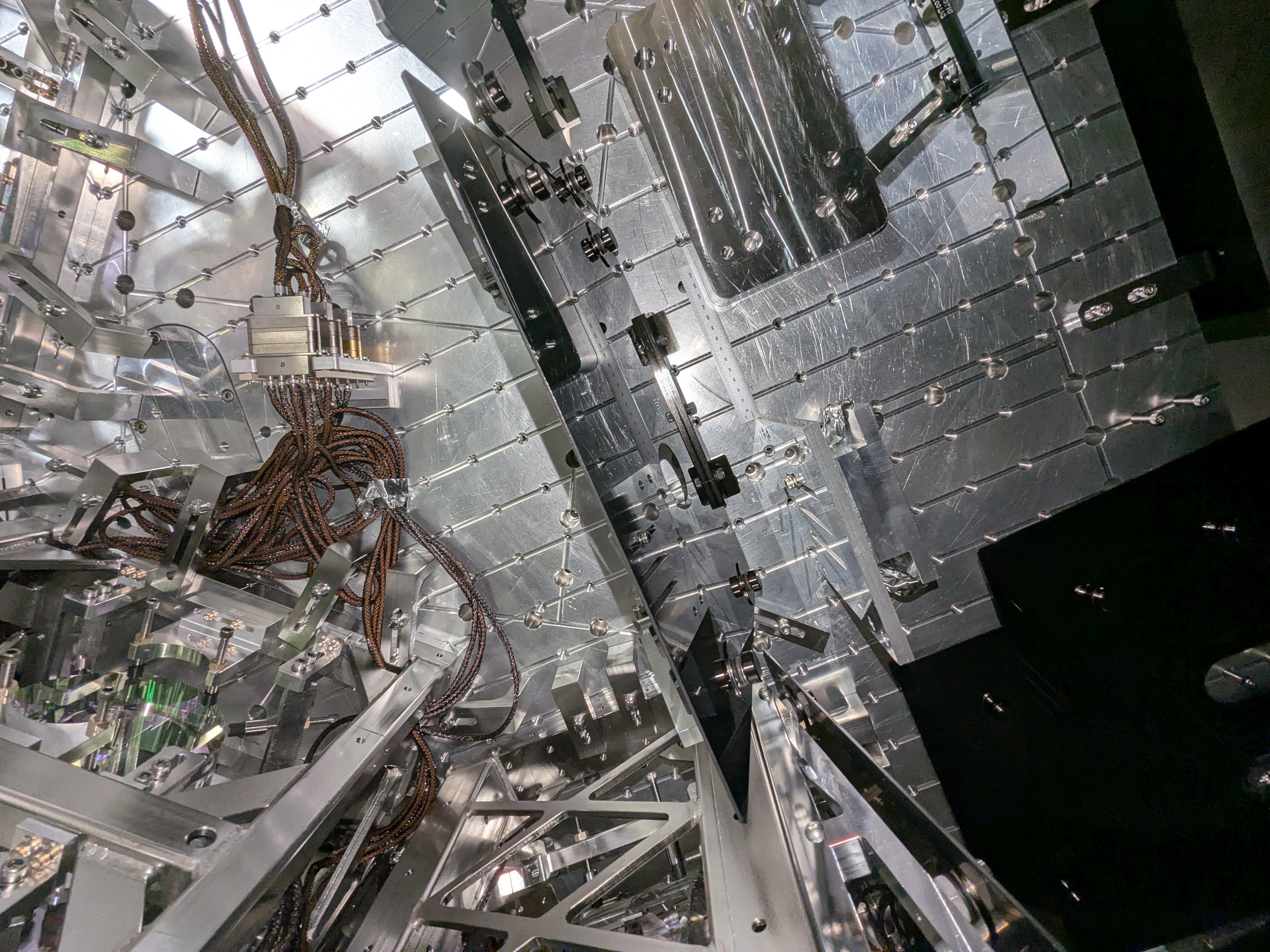
IM4_TRANS path optics (pickoff for the ISS path, pico for IM4_TRANS centering) as well as the IM4_TRANS QPD itself seemed to be firmly attached to the pole and the ISI table. I grabbed them using my hand and wiggled and they didn't move at all.
The beam is level between IM1 and IM4 and then goes up toward PRM, but I cannot easily find how much. So here's a quick note.
| MC3 | IM1 | IM4 | PRM AR | PRM | |
| Height [mm] | 155.5 | 155.5- | 155.3 | 158.8 | |
| Angle [rad] of the exiting beam relative to the horizontal plane | level | 8.5m | 628u | 628u |
Nominal height of MC1 and MC3 center is 155.5mm (D09010088, D0901089). IM1 beam height should be pretty close though MC2-MC3 line is not level.
The beam from PRM HR to PRM is tilted up by 0.035966 deg = 628urad (I'm using the PIT angle of PRM itself in D0901920 rather than reading the coordinates of PRM and PR2).
PRM has 1 degree vertical wedge (D0901172), the bottom being widest, so the beam is tilted up from IM4 to PRM AR by ~(n-1)*1deg = 0.4497 deg relative to the PRM-PR2 line, n being the refractive index of fused silica for 1064nm (1.4496).
The beam from IM4 to PRM AR is therefore tilted up by (0.4497+0.035996) = 0.4857 deg = 8.5 mrad relative to the horizontal plane.
PRM center height is 158.8mm nominal (D0901090) and the distance from PRM AR to IM4 is 415.9mm (T0900486), so the beam height at IM4 should 158.8-415.9*8.5mrad = 155.3mm, which is good enough of an agreement with MC3 height.
FYI I measured the IM4 baffle height this morning and it was (206+104)/2 =155mm, so the baffle height should be correct. (The beam is low on that baffle though YAW is the worse problem than PIT.)
[Keita, Rahul, Elenna]
Today I moved IM2 and IM3 to bring the beam back to our reference position on IM4 trans QPD and center it on ISS QPD after Keita's move of the mode cleaner mirrors in 90259. This requires some iteration back and forth on both suspensions.
Our desired positon on IM4 trans is P = 0.22 and Y = -0.06. On ISS QPD, it is centered, so P=0 and Y=0.
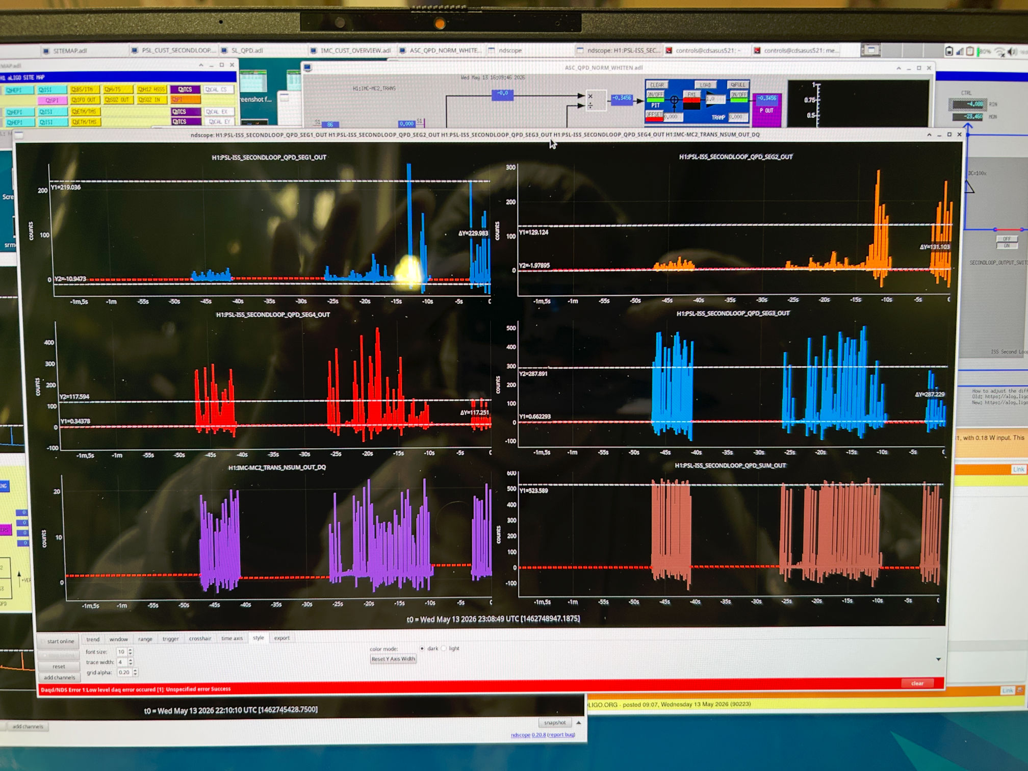
We are driving MC2 in length, so the mode cleaner is flashing, and there are bright flashes on the QPDs. I am pausing ndscope on a flash and measuring the height of the peak in the fast channel and calculating the pit and yaw position from each QDP segment.
| Start | End | ||
| IM2 P slider | 765 | IM2 P slider | 810 |
| IM2 Y slider | -187.7 | IM2 Y slider | -88.7 |
| IM3 P slider | -560.7 | IM3 P slider | -614.7 |
| IM3 Y slider | 320 | IM3 Y slider | 385 |
| IM4 trans PIT | 0.390 | IM4 trans P | 0.268 |
| IM4 trans YAW | 0.450 | IM4 trans Y | 0.010 |
| ISS QPD PIT | -0.379 | ISS QPD PIT | -0.059 |
| ISS QPD YAW | -0.455 | ISS QPD YAW | 0.08 |
Unfortunately, this still results in clipping on the baffles Keita notes above, so we will keep going.
At the nominal IM4 trans position, yaw is pretty well centered. I then moved IM2 to both edges of IM4 trans QPD.
I changed the IM2 yaw slider to -250.7, which brought the yaw position on IM4 trans to 0.85. This made the clipping worse.
I changed the IM2 yaw slider to 90.3, which brought the yaw position on IM4 trans to -0.88. This was still not good enough to fix the clipping on the baffle.
By making a very large move to IM2 yaw slider value of 710.3, this centered the beam in the IM4 baffle. This is a ~800 urad move according to the osems and slider. The IFO REFL beam is still clipped.
I undid the 800 urad move, so the IM2 yaw slider is back to -88.7 for now.
Keita and Rahul went out to measure the position of the beam on MCs 1,2 and 3. We think that we need to make a move of these three mirrors to see if we can unclip the beam on these baffles that way.
We want to note that the positive yaw move of IM2 corresponds to unclipping on the IM4 baffle, this is consistent with the beam motion observed in chamber in the -X direction. However, this is contradictory to the sign on IM4 trans QPD, which was moving to negative yaw when we did this move. We suspect that the segment defintion must be wrong somewhere.
Keita will say more later once we have a chance to analyze the positions in chamber.
To clarify, the slider values of IM2 and IM3 are left at the "end" positions on the table above.
I trended the power measured at IM4 trans compared to the IMC input power for the entirety of the run. Some notes:
Because of this recalibration, I decided to compare both the IM4_TRANS_INMON and IM4_TRANS_OUT16 to IMC-PWR_IN_OUT16
FM10 in the IM4 trans filter bank is a factor that Craig and Georgia determined in the alog linked above, 4.606. I trended the inmon channel and multipled it by this number, ignoring other calibration factors present in the filter bank.
Therefore, the plotted ratio of IM4_trans [IN, OUT] / IMC power IN will help us understand how the power at IM4 trans changed throughout the run, like perhaps if the amount of clipping on the way to IM4 has changed.
I am comparing the ratios of both IM4 trans IN and OUT just in case we get confused by the changing calibration of the diode. I took an hourly median of these channels so we are not confused by random variation and masked the times to only show when IMC lock was either in state 100 (locked) or 70 (ISS ON).
Overall, the amount of power arriving on IM4 trans has definitely changed throughout the run.
Notably, during the vent between O4a and O4b, the amount of power measured at IM4 trans dropped. We chose not to move the IMs, and instead Sheila picoed to recenter on IM4 trans, linked above. Another power drop occured again during O4b. This time, we moved IMs to fix it. At the start of O4c is when Sheila and I recalibrated the diode, hence the disagreement with IN and OUT channels.
The second plot attached shows how the pitch and yaw on IM4 trans has varied alongside the power.
Based on what Keita can see happening in the chamber with baffle clipping, it is possible that during these alignment shifts, the amount of clipping in HAM2 on the IO baffles was changing, so the amount of power making it to IM4 trans and the amount of power going into the IFO was changing.
Specifically, I want to emphasize that with Craig's integrating sphere measurements in HAM1, we assumed that all loss between HAM1 and the PRM in HAM2 was known, i.e. loss from the IFI, etc. However, if there was additional loss on that path that changed with input alignment shifts, that would explain the apparent IM4 trans power changes during O4. Notably, Sheila and I recalibrated IM4 trans in O4c because after we fixed the input alignment in late O4b, we got more power on IM4 trans than we had gotten all run (see the jump around day 600 on the attached plots). I thought this was not physically possible, so we adjusted the calibration. Perhaps instead, we changed the amount of clipping in HAM2, giving us more light on the PRM than we had seen all of O4.
This may also help explain some of our arm power measurement mysteries if we actually had less input power than assumed.
I just want to add a clarification that we have been trying to replicate the alignment onto IM4 trans QPD, so we are trying to align to the previous pitch and yaw position. However, for O4, the beam was nearly falling off the ISS QPD, so we don't want to replicate that alignment (the pitch and yaw values on ISS QPD were like +- 0.9). We have decided to go with centering the beam on ISS QPD, especially since we have adjusted the ISS pico mirrors to find that alignment.
Clipping on IFO REFL baffle is gone.
The problem of IFO REFL beam clipping by the last IFO REFL baffle in HAM2 (see alog 90251, especially this picture) seems to have been caused by a huge PRM change in the PRM alignment sliders made on Monday May/11/2026 past 1700 local time (that none of us knew/remembered/understood).
Once Sheila reverted PRM back to March/2026 alignment, changing the IFO REFL beam path (but not the alignment into ISS path), IFO REFL was not clipped any more even though it looked low on the baffle (IFOREFL_baffle.mp4). LSC and ASC REFL sensors on HAM1 ISI saw the flashes right away without any adjustment of RMs, and the flash peaks were already reasonable. According to Sheila, compaing to a time when DRMI was acquiring in November:
All of these were a good sign.
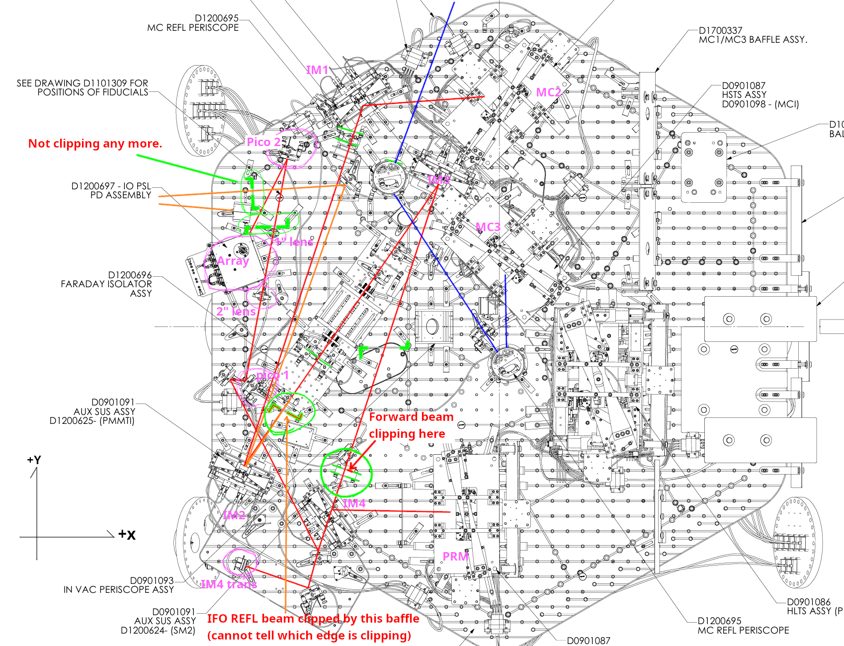
Forward-going beam into the IM4 is clipped by the baffle in front of IM4, and the IFO REFL beam is clipped by the baffle at the -Y edge of the IFI.
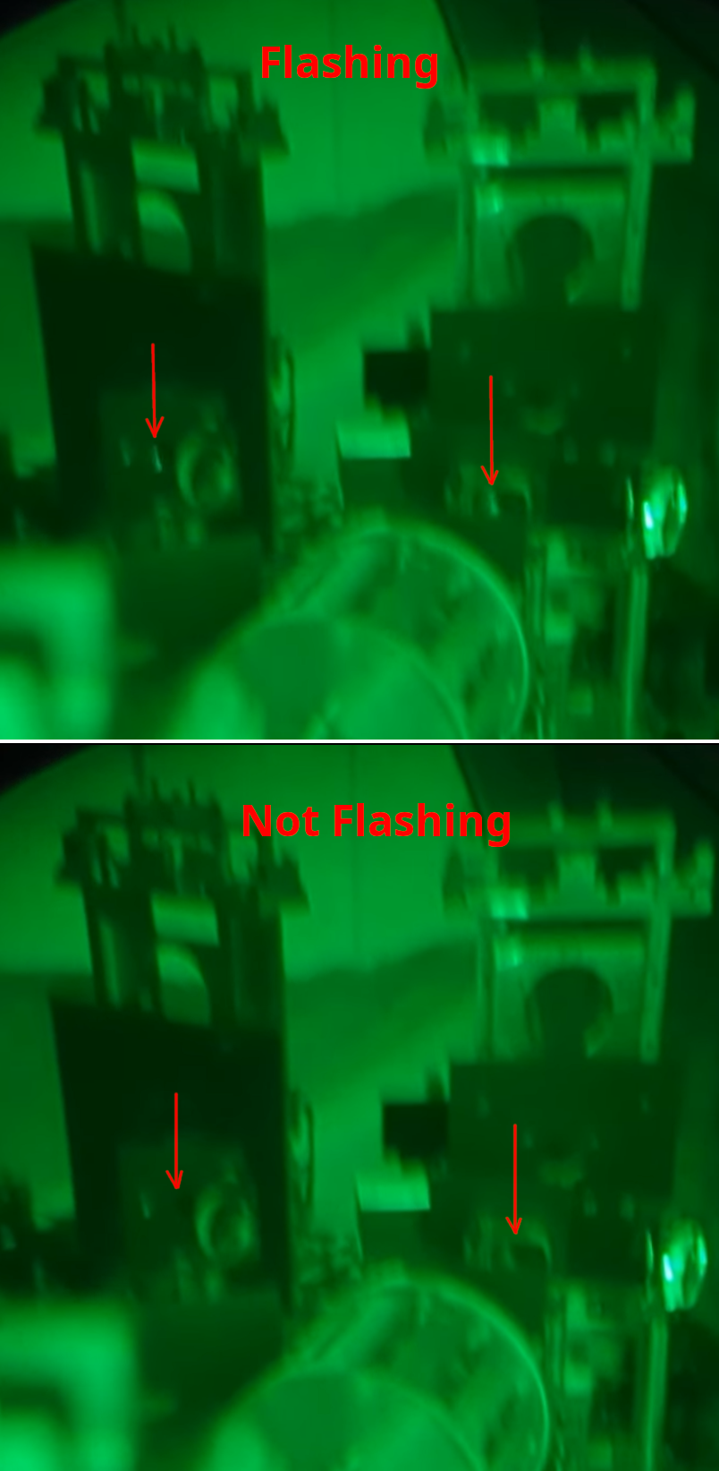
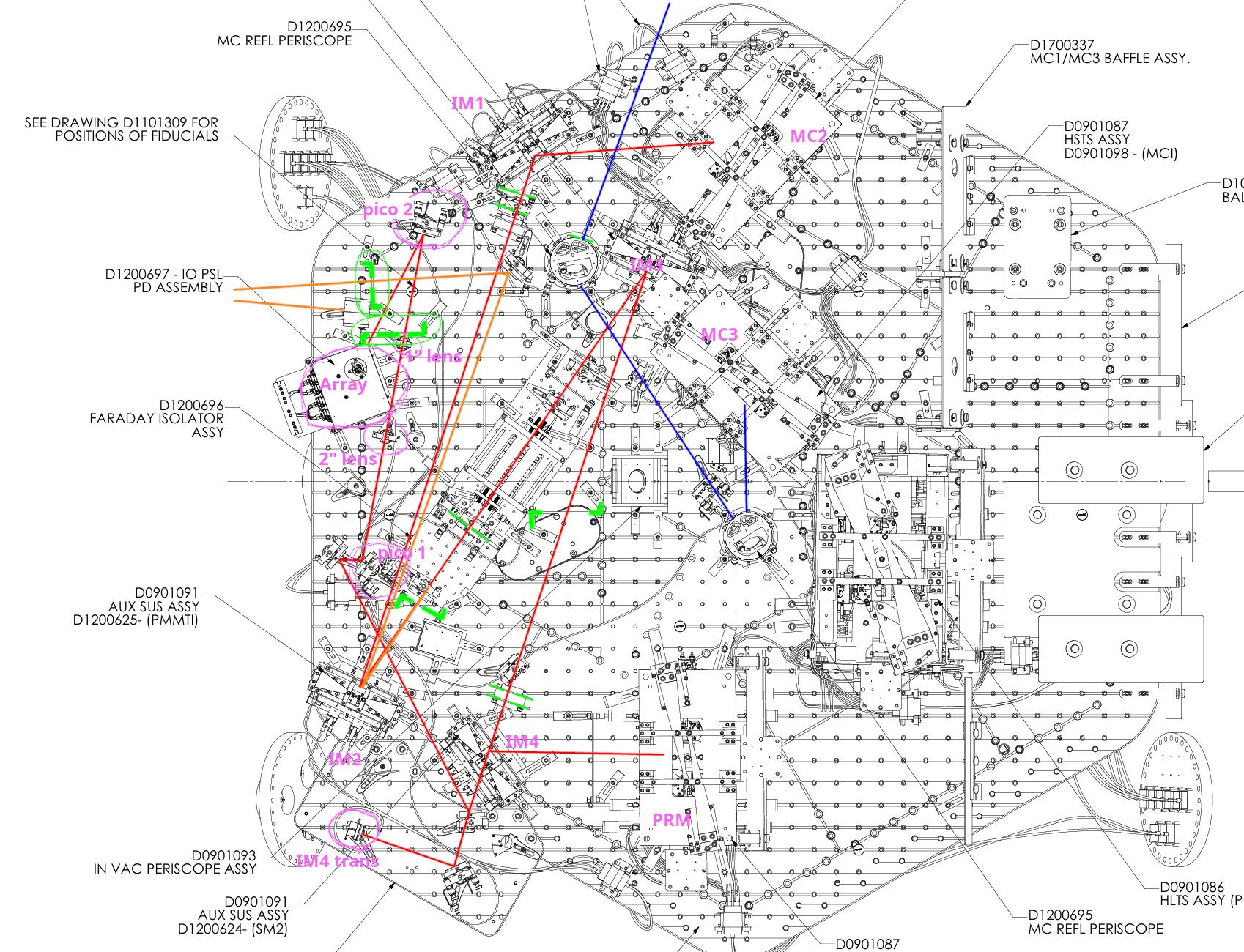
Unfortunately I've found that there were two other clipping points that I must have missed yesterday using IR viewer. See clipping.png, sorry for a blurry through-IR-viewer picture shot from the distance. Go back to HAM2layout_annotated2.png to figure out which baffle is what.
There's a baffle in front of IM4 between IM4 and IM3, and the forward-going beam is slightly clipped at the +X edge of that baffle.
Also the IFO REFL beam is clipped by the baffle installed at the -Y edge of the IFI. I know this is IFO REFL because the bright spot goes away when I block the beam on PRM by a sheet of aluminum. I cannot quite tell from the picture which edge of the baffle is clipping, but I think it's also +X edge.
In the past, when PRM spot position was measured with full IFO, it was like a mm off according to Sheila, so it's hard to imagine that the beam was clipping on the baffle in front of IM4.
Changing IMC alignment (trial 1, didn't fix clipping).
We decided to back off the changes we've made for MC1, 2 and 3 since Monday and revert back to in-vac March alignment. If we have to make a huge adjustment to JM3 to follow the IMC, maybe the beam coming from JM3 is suspect (which means that the MC2 trans path is somehow suspect too).
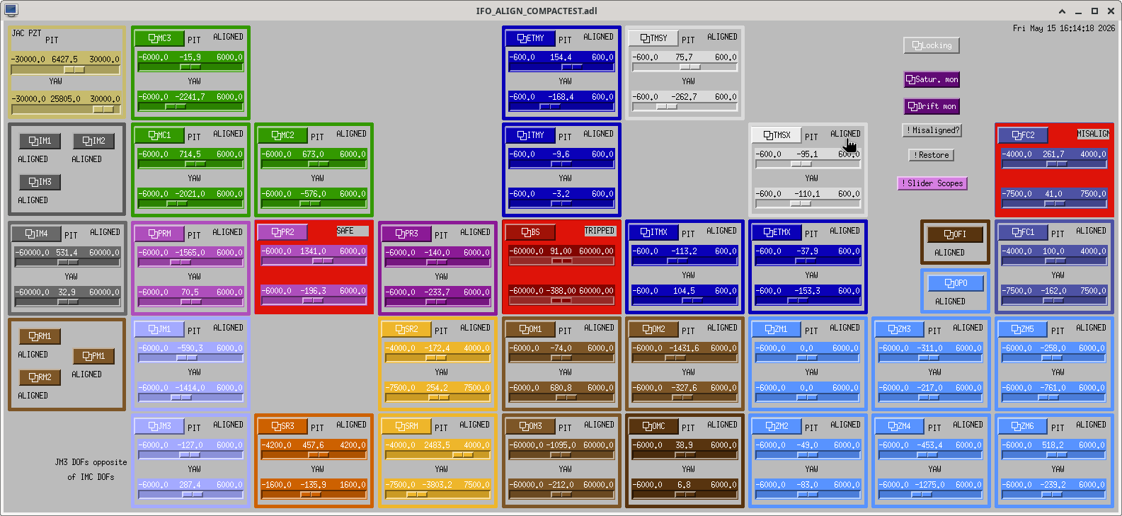
Before I did anything, the starting point was captured in alignment_2026-05-15_16-14-21.png.
MC1/2/3 was reverted just based on slider values and not using OSEM readings as per alignment_2026-03-18.png.
Then JM3 was adjusted in PIT and YAW to give the maximum transmission measured in IM4_TRANS_NSUM. Actually I didn't move JM3 as much as I expected.
That alone couldn't recover a good 00 mode flashing so I moved MC2 and MC3 to follow the input beam. MC2 moved back closer to the position this morning.
After that I felt as if it was somehow easier to optimize further using MC1 as well as MC3, thinking that it would be a minor adjustment but somehow ended up moving MC1 by a large amount after iterations.
My end point is captured in alignment_202605151726_sliders.png.
Without IM3 and IM2, the beam was still on IM4_TRANS as well as ISS QPD, the flashes were good, so I looked at the clipping on the baffle in front of IM4 as well as the baffle at the -Y edge of the IFI, and they were still there. IFO REFL baffle was still not clipping.
Will have to think about what these all mean.


Good news is that we're done with the alignment of the ISS path. Pictures and details are to follow.
Then I reinstalled the last IFO REFL baffle right in front of the HAM2-HAM1 septum window. (The baffle was removed after marking the exact position using three temporary dog clamps on the ISI on day 1 because it was in the way, I was supposed to record that in alog 90158 but forgot. I'm absolutely sure that the position of the baffle was restored within 0.1mm of the original position.)
Bad news is the IFO REFL was clipped on that baffle. 00 mode flash isn't clipped that much but horizontal modes certainly are. That was not THAT surprising because the IMC alignment was/is not great (see my comment 90224). This looks to me that the uncontrolled degree of freedom of the IMC is wrong regardless of the reason why a huge alignment change had to be made to center the MC2 TRANS QPD.
Good news is the ISS path alignment is not impacted by that, at least greatly, because we made sure that the beam hit the right location of IM4 TRANS as well as ISS array QPD before we did anything in the ISS path. Note that the baffle clipping the beam is not in the ISS path.
In other words,
However, since we don't want to revisit HAM2 once we close it, I'd like to understand what's going on for the IMC/IFO alignment.
For location of things, refer to HAM2layout_annotated.png. Blue line = IMC reflection. Red line = IMC transmission. Orange line = IFO REFL rejected by the IFI. Green things are baffles (two-hole baffle and the last IFO REFL baffle are circled in green).
The alignment status at the start of Thursday morning:
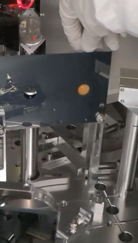
The beam was very high on the two-hole baffles but was OK on the input hole of the ISS array. See alog 90237, see this picture as well as this, and this video. This just meant that we were shooting down the beam from the 1" lens toward the center of the array QPD.
Work done on Thursday:
We moved the beam down using the two pico mirrors such that ultimately the beam goes through the center of the input hole of the array and reasonably centered on QPD.
Detailed procedure was:
We have found no unexpected behavior here, I was surprised that the process was easy and things made sense given the difficulty people had in the past to improve alignment of the array in vacuum with the old unit. That's probably because the beam was already clipping back then.
The only thing was that the YAW actuator of the second pico mirror didn't have much range to start with even before we moved anything. At some point it didn't hit its end of the range but was close (2nd_pico_position_before.jpg). Since we need a healthy headroom for adjustment both ways, I relieved the pico by mechanically rotating the pico mirror assy (2nd_pico_position_after.jpg).
IFO REFL beam was clipping on the baffle:
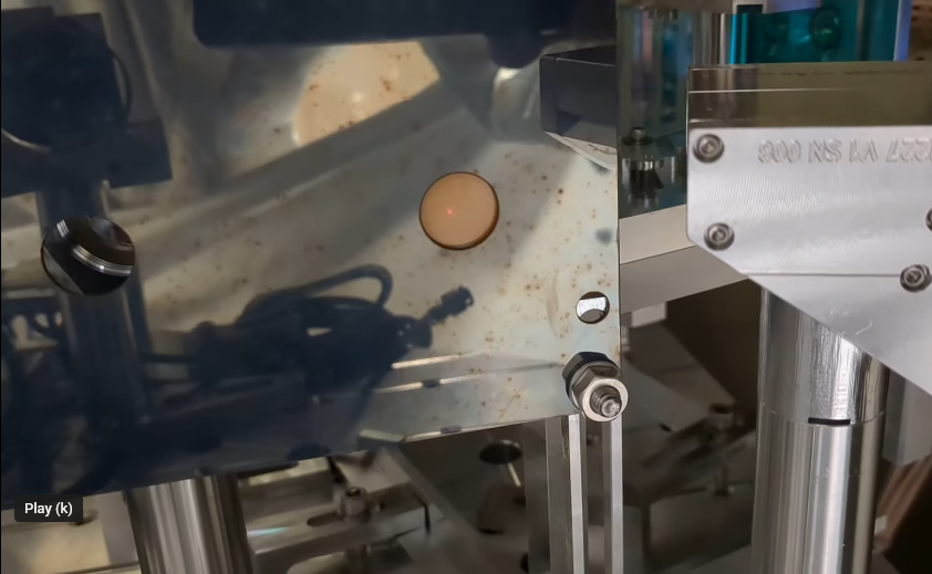
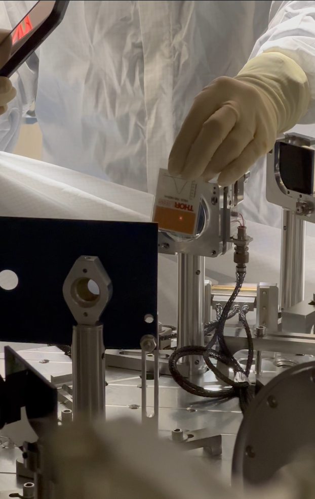

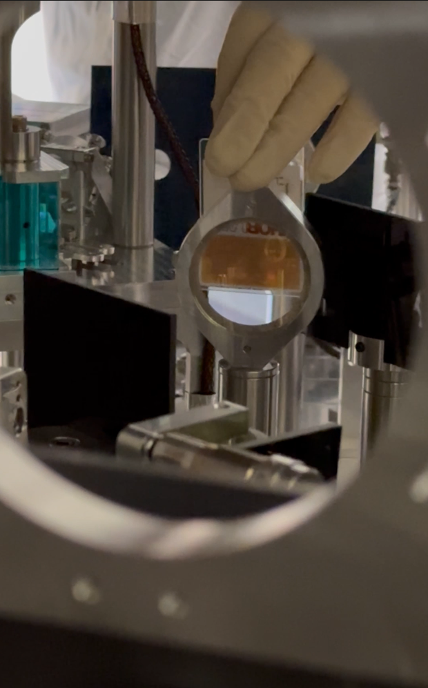
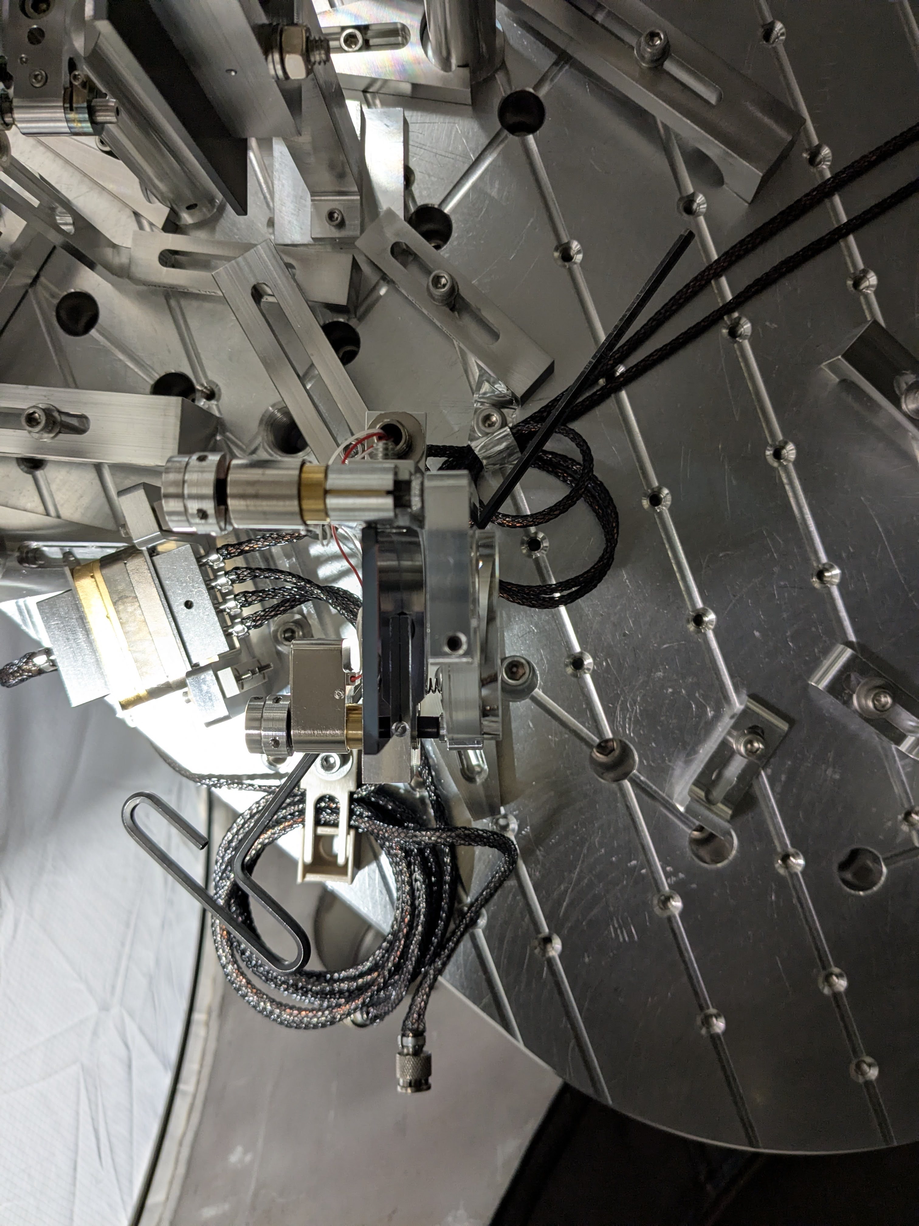


Following yesterday's alog 90219:
At this point I and Rahul checked the beam positions in HAM2. Some things to note:
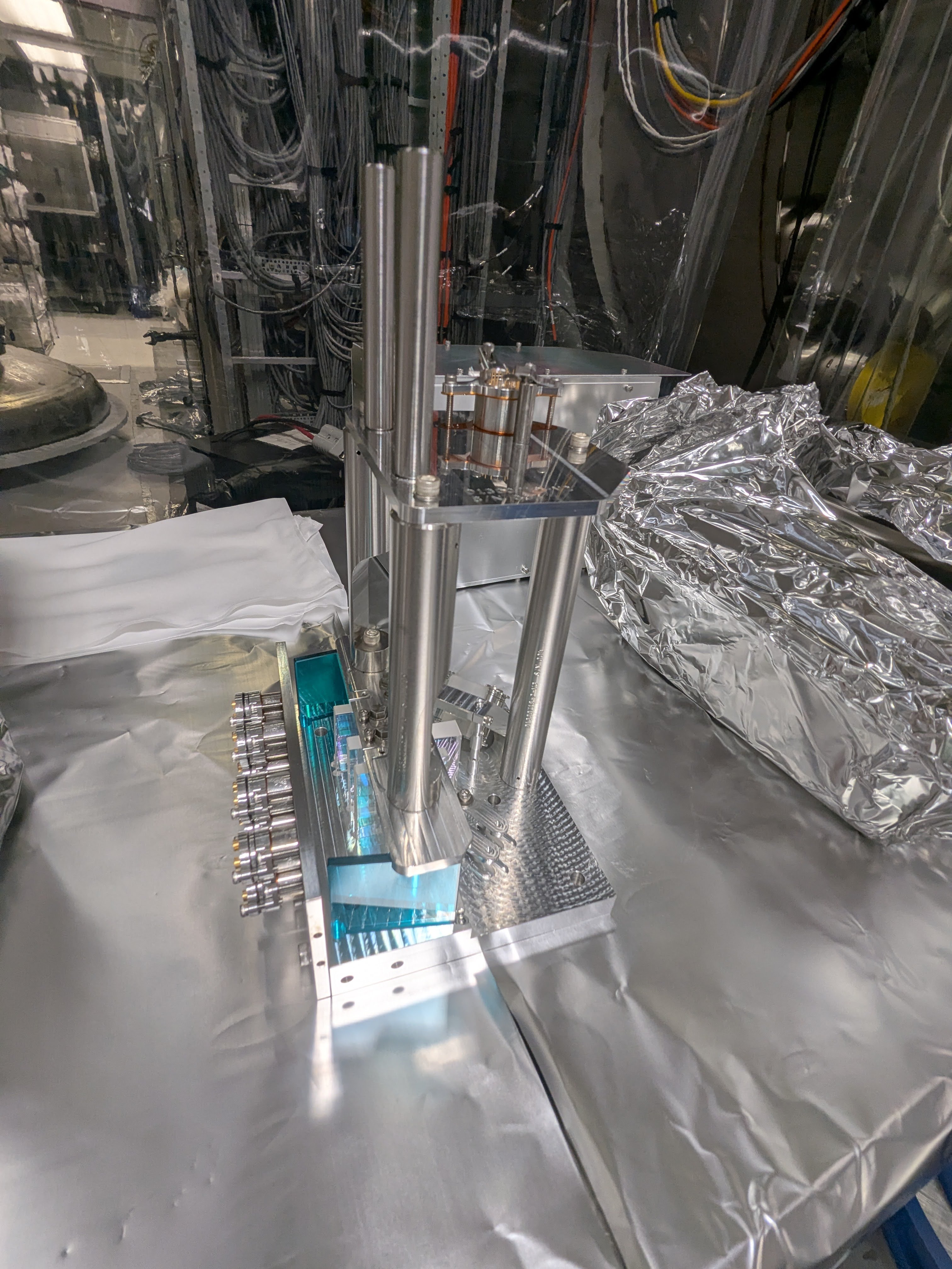
We proceeded to swap the ISS array unit.
At this point we saw flashes on QPDs as well as array PDs right away. INNER as well as OUTER SUM flashes were both about 0.06 (in the old unit it was 0.03 for OUTER but INNER was much smaller).
We started trying to center the QPD using the first pico mirror. Since pico driver is temporary unavailable (IOT2L is moved away) Rahul turned the pico manually while Elena looked at the laptop screen to monitor flashes in the individual segments. We managed an OK job (arrayqpd_centered.jpg) and checked the beam spots again.
The baffle height might not be the same as the lens height and/or the ISS array input hole height, but otherwise it seems that we're shooting down the beam from the 1" lens to the ISS array. We'll check if the lens, baffle and the array are all at the same height or not, and decide how to proceed.

1st: Rahul is disconnecting the QPD cable.
2nd, 3rd (photo by Betsy): Rahul in chamber (me outside).
4th: Old unit was extracted. This is S1202971.
5th: New unit (S1202965) to the left, old one to the right.
6th: Rahul after successfully connecting up the new unit in chamber.
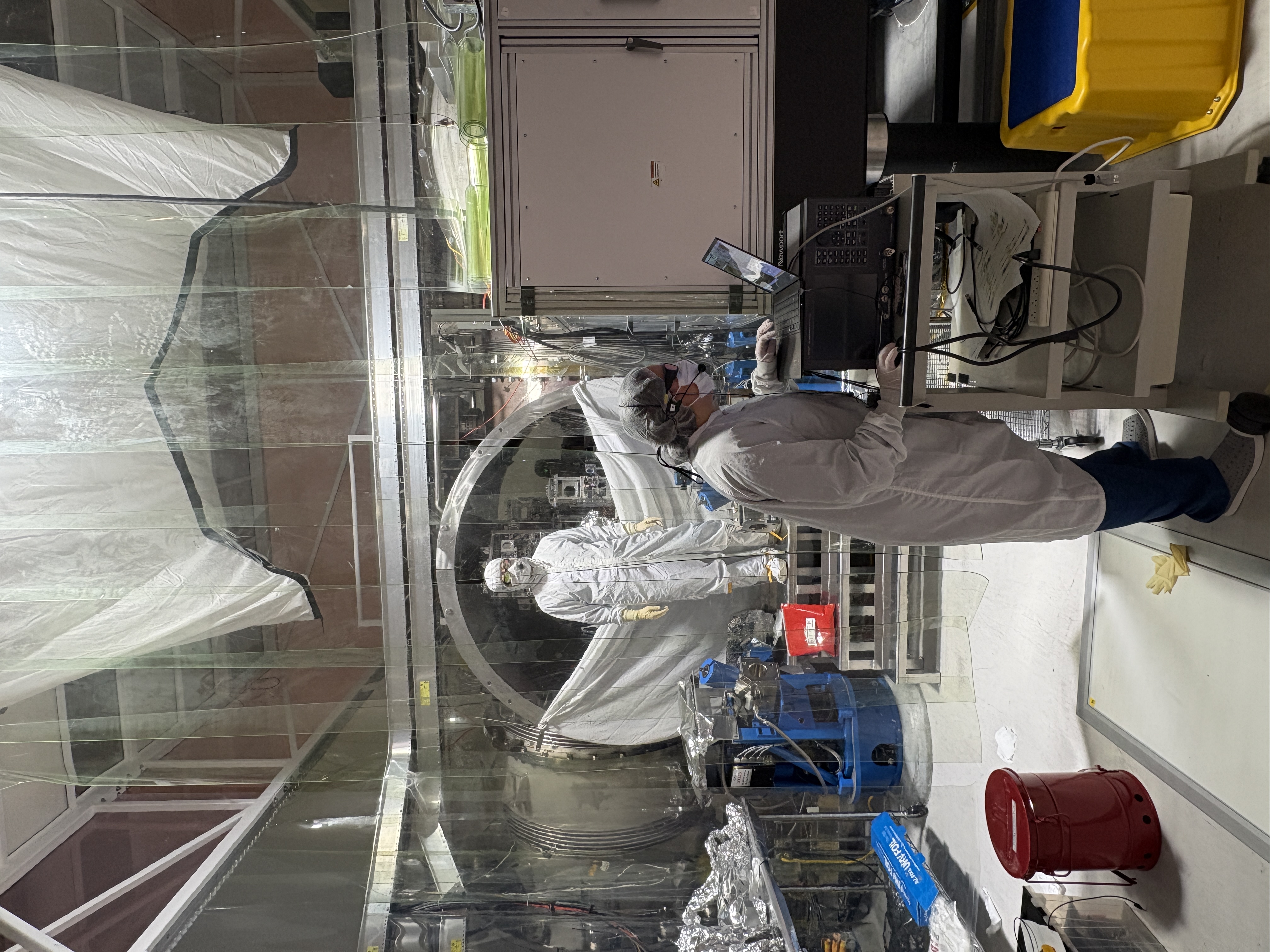
7th (photo by Betsy): Elenna (front) is checking the QPD centering, Rahul (a shadow in the back in this photo) is manually moving the pico mirror from -Y door, and I'm somewhere inbetween just observing the two doing a good job.




epo tagging for photos!
Attaching two pictures in reference to Keita's comment above - "The beam was very high on the left hole of the two-hole baffle (Rahul has a good pic), high on the right hole (right_hole_after_new_array_QPD_centered.mp4)"
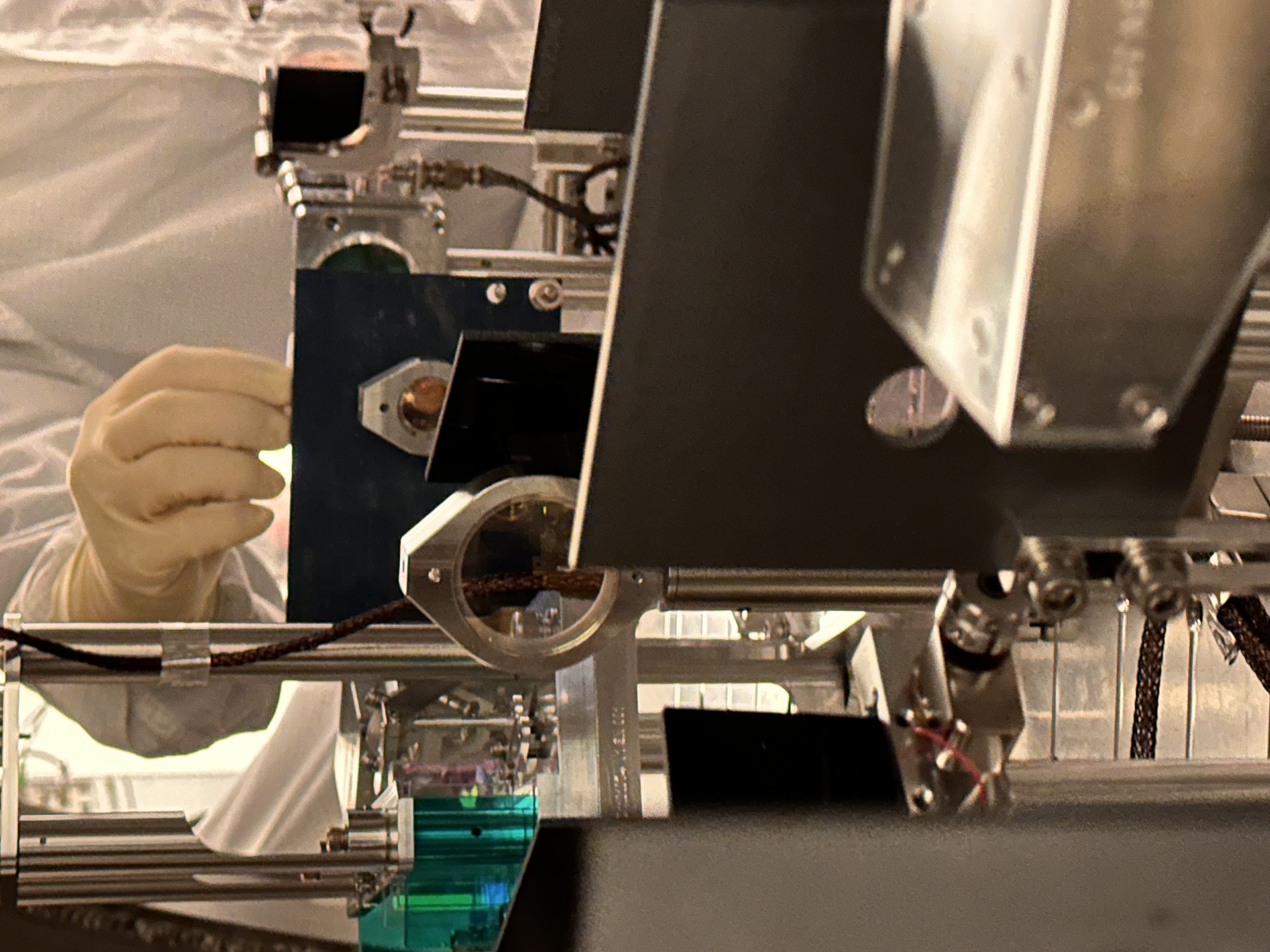
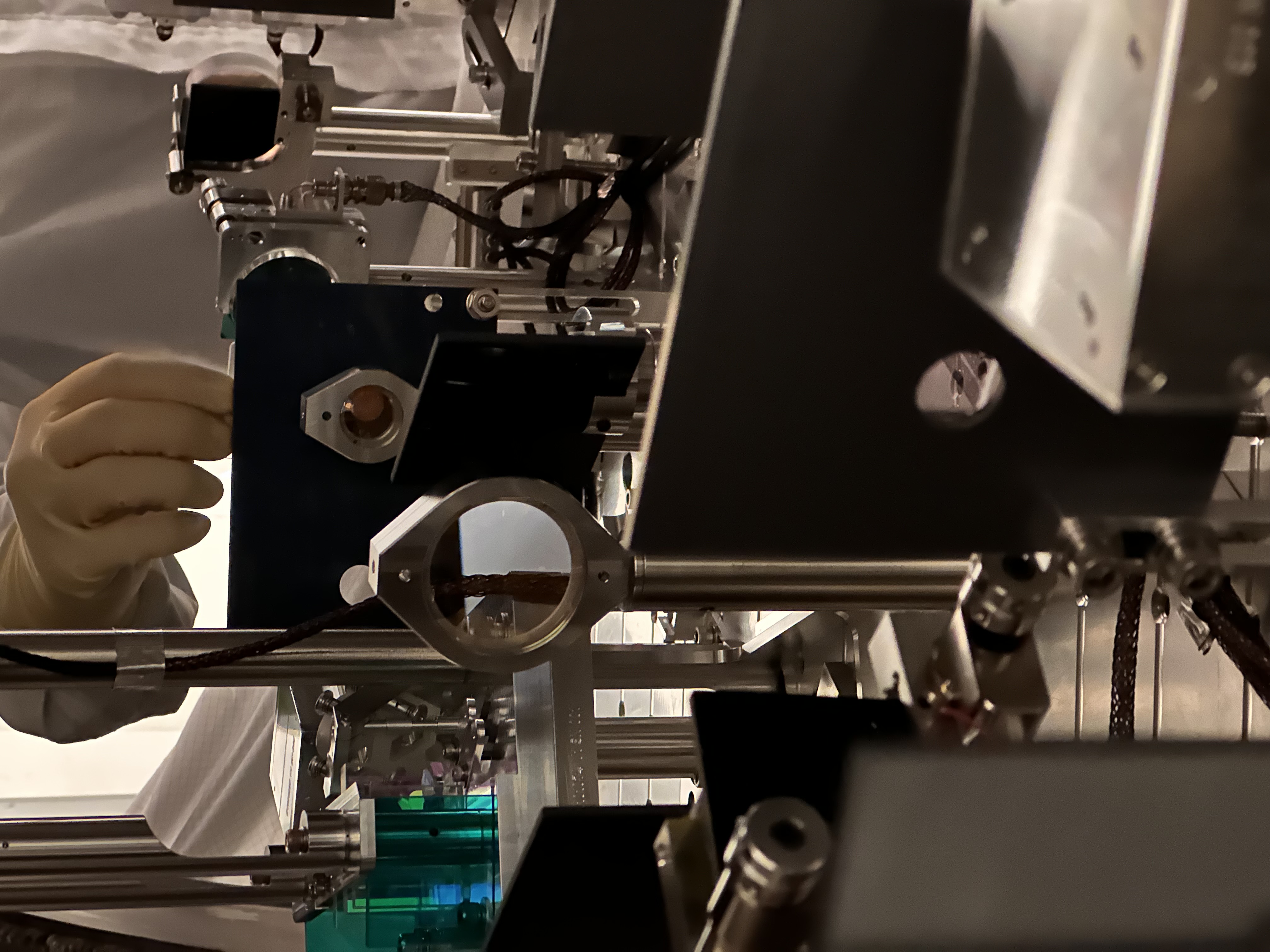
We concluded that the height of the baffle and the array unit are both correct, the beam is really too high on the 1" lens and we're shooting down from there to the QPD. (This should have been the case for a long time with the old unit. Right after the new unit was installed the beam was on QPD and the beam stayed on the QPD, the diameter of the QPD is 3mm, i.e. we haven't made any huge change on the height of the beam at the left baffle hole.)
With this information, what we'll do next is to gradually bring down the height of the beam on the left baffle hole using the first pico mirror, and use the second pico mirror to bring the beam back on the QPD, until the beam line into the array becomes level-ish with the ISI surface. It doesn't have to be perfect but we don't want to be this much tilted.



Restored the alignment sliders for IM2 and IM3 back to Monday values ([IM2P, Y] =[765, -187.7], [IM3P, Y]=[-560.7, 320]).
Measured the flashes. Chose the flash that gave the MC2 trans sum maximum power, which in general agreed with IM4 trans sum max but didn't with ISS QPD nor array PD inner sum nor outer sum.
Anyway,
PIT and YAW numbers were after normalization divided by (seg1+2+3+4), not by SUM, so there's a small difference but that doesn't matter at this point.
IM4 TRANS and ISS QPD PIT and YAW are broadly in agreement with Jenne's alog 90206 i.e.
I haven't compared the ISS Outer SUM with March 2026 when IMC was locked with 2W. Somebody check please. We'll go into chamber and start checking the beam path.
On March 11 when we locked the IMC at 2 W, the outersum was 0.062. Today, I measured the outersum flashes (relative to the dark noise) to be 0.031, with 0.18 W input. This means our alignment into the ISS has improved relative to March.
We started with yesterday's alignment. I checked flashes in ISS array PDs and didn't like that the balances between them were very much different from how they were when IMC was locked back in March.
Then we started changing IM2 and IM3 to see if we can get back, but I was appalled that the flashes became stronger and stronger on array PDs as we aligned, which probably means that the beam was almost falling off of the PDs when we started.
That shouldn't have stopped us because we don't know where the beam was on the array PDs when MC was locked (people gave up optimizing that path because things didn't make sense), it could have been falling off of the diode (because each diode is 2mm, QPD is 3mm, the beam size is ~250um or so, and the beam was almost in one quadrant of the QPD). But I started thinking about many what-ifs and wasted time.
After all, since IM4 TRANS and ISS array QPD are both reasonably close to March 2026 position, we know that the beam position as well as angle of the beam injected into ISS path from IM4 are already close to those when IMC was good in vacuum.
What we should do is this:
Other things to note:
This is not required for the alignment but it's helpful to know how much we can move the beam on QPD. In an unlikely event where we somehow lose the beam in vacuum on the array QPD after IMC is locked, we might be able to scan IM3/IM2 to regain the beam on QPD, and slowly move IM3/IM2 back to the nominal position while pico-ing so the beam isn't lost on the QPD. If the beam is not clipped, the beam displacement on the QPD is ~3mm per 1mrad of IM3 rotation using parameters collected from various documents, see attached script.
The same script shows you that the Gouy phase separation between two pico mirrors is 10 degrees (if we use the beam parameter in Matt Heintze's alog 12537, which was probably obtained by the measurement of the bypassed beam) or about 20 degrees (if we use IMC eigenmode parameter propagated to the ISS path using D1200693).
Another thing is, if we believe the design eigenmode number rather than the measured bypassed beam in Matt's alog, the beam waist will be smaller and at about 20cm upstream of the PDs. The beam size on the PDs is about twice as large as it should be (470um rather than 250um). I cannot measure the beamsize of the flashes so we won't do anything, but that's something to remember. If IM3 has enough actuation range, we can later lock the IMC, scan the beam across the PD until the beam falls off, see how sharp the fall-off is, and use the diameter of the PD (3mm) to determine the size of the beam. Maybe a good project for a fellow.
One of the things that bothered me (that isn't directly related to ISS alignment) is the fact that we had to rotate JM3 by a huge amount, i.e. negative 200um in PIT to "center" the MC2 trans QPD. This is the equivalent of the negative YAW rotation of the beam in IMC's coordinates (clockwise seen from the top). Since the distance between MC2 and JM3 is ~19m according to E2400218, this means that the MC2 beam position was moved by about ~7.6mm in -Y direction on MC2. This seems to roughly corroborate with the pictures in alog 90203 ("before" picture and "after", hard to tell how much it actually moved due to parallax but there's no doubt that the motion was large).
What if this is because something is wrong with the MC2 trans path? Like the pico mirror in front of the QPD was bumped (by a huge amount, however unlikely it is). My conclusion is that we can lock IMC in vacuum, use WFS with MC2 centering, measure the centering on MC2 using dither, and figure it out. If QPD center is grossly off from the MC2 center, we can pico.
Sorry the script in the above alog didn't work because it was missing one line.
Attached is a working version. You need a la mode matlab package https://github.com/nicolassmith/alm.