**Short version: Increased RY input motion (maybe HEPI, maybe wind/ground) causes ISI X loops to ring up when running 45mhz blends. The suspension/tidal is not the cause. The 90mhz blends seem to be immune to this. Other than using 90mhz blends, I'm not sure how to fix the ISI's configuration, short term to prevent the ISI from ringing up. But we should put a StripTool of the end station ISI St1 CPS locationmons somewhere in the control room so operators can see when ground tilt has rung up an ISI. Alternatively, we could add a notification to VerbalAlarms or the DIAG node when an ISI has been moving something like 10 microns peak to peak for several minutes.
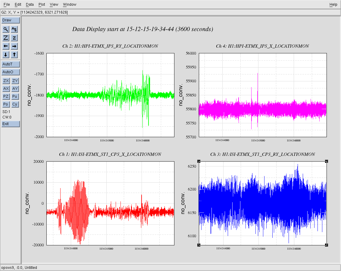
This morning while the IFO was down for maintenance, Evan and I looked at ETMX to see if we could figure out what is causing the ISI to ring up. First we tried driving the L1 stage of the quad to see if some tidal or suspension drive was the cause. This did not have on the ISI, so I tried driving on HEPI. When I drove HEPI X, the ISI rang up a bit, but no more than expected with the gain peaking of the 45mhz blends. When I drove HEPI in RY, however, the ISI immediately rang up in X, and continued to ring for several minutes after I turned the excitation off. The attached image shows the ISI CPS X(red), RY (blue), HEPI IPS RY(green) and X (magenta). The excitation is visible in the left middle of the green trace, also visible in the sudden increase in the red trace. I only ran the excitation for 300 seconds (from about 1134243600 to 1134243900), but the ISI rang for twice that. After the ISI settled down I switched the blends to the 90mhz blends and drove HEPI RY again. The ISI moved more in X but it never rang up even after I increaed the drive by a factor of 5. The second plot shows the whole time series, same color key. The large CPS X motion (with barely noticeable increase in the IPS RY) is the oscillation with the 45mhz blend , the larger signal on the IPS RY (with small increase in CPS X) is with 90mhz blends. The filter I used for each excitation was zpk([0 0],[ .01 .01 .05 .05], 15111).

Did a bit more analysis of this data -
Not sure why things are so screwy.
There might be non-linearity in the T240s.

Jim's entry indicates that it is NOT a servo interaction with the tidal loop.
so it is probably something local - still not really sure what. Based on the plots below
I strongly recommend a low-freq TF of Stage 1 (HEPI servos running, ISI damping loops on, iso loops off)
drive hard enough to push stage 1 T240s to +/- 5000 nm/sec

what I see
fig 1 (fig_EX_ringingXnY)- time series of X and Y and drive signal
- This is the same as Jim's data, but we also see significant motion in Y
- In the TFs we need to look for X and Y cross coupling

fig 2 (fig_X_ringup_time) - this is the time I used for the other analysis -
We can see the CPS-X and T240-X signals here. Note that I have used bandpass_viafft to keep only data between 0.02 and 0.5 Hz.
The T240 and CPS signals are clearly related - BUT - does the T240 = derivative of the CPS?
signals are at input to the blend filters

fig 3 (fig_weirdTFs) - These are some TFs from ST1 X drive to ST1 CPS X and from ST1 X drive to ST1 T240.
If all the drive for X is coming from the actuators, then the CPS TF should be flat and the T240 TF should be Freq^1
The CPS TF looks fine, I can not explain the T240 TF
The coherence between T240 and CPS sigs are in the bottom subplot

fig 4 (fig_coh) Coh for drive -> CPS, drive -> T240 and CPS->T240. All are about 1 from 0.03 to .15 Hz.
So the signals are all related, but not in the way I expect.
NOTE - If the ground were driving a similar amount to the actuators, then these TFs would be related by the loops and blend filters -
I don't think this is the case. decent driven TFs would be useful, here.

fig 5 - sensor_X_difference : Take the numerical derivative of the CPS and compare it to the T240 as a function of time.
Also - take the drive signal * 6.7 (plant response at low freq from TF in fig 3) and then take the derivative of that.
These 3 signals should match - BUT they do not. The driven plant and the CPS signals are clearly similar, but the T240 is rather different looking, esp in the lower subplot. As if the higher frequency motion seen by the CPS is not seen by the T240.
What the heck?

fig 6 - fig_not_gnd - could it be from ground motion? So I add the ground motion to the CPS signal - but this doesn't look any more like the T240 signal than the straight CPS signal. So the signal difference is not from X ground motion.

Has the tilt decoupling on stage 1 been checked recently? with the 45mhz blends running we are not far from instabilty in this parameter (a factor of 2 maybe?)