hugh.radkins@LIGO.ORG - posted 11:27, Thursday 29 March 2012 (2501)
HAM3 Electrical FeedThrus Protected
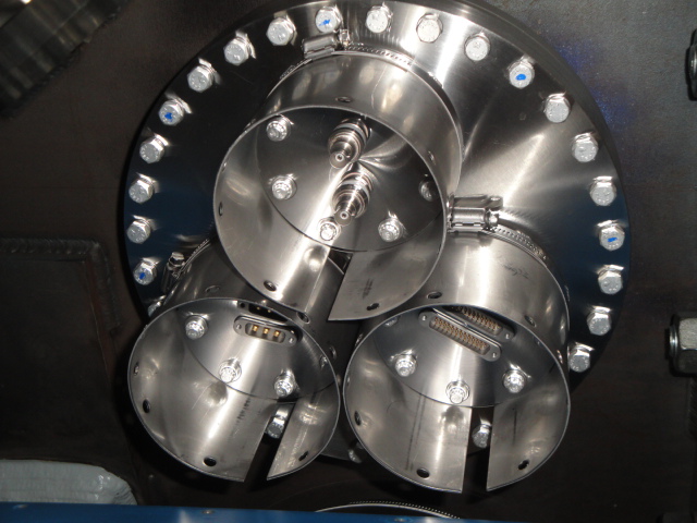
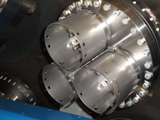
Following the ICC/Feedthrus Installation, once the Cleanroom was moved, I installed the FeedThru Protection Shrouds aka LCP (Leak-Check Preventor.)
It is sort of a shame that the most vulnerable style FeedThru was located on top but it is now protected.  These are the 4" deep Shrouds and do shield the FeedThrus well.  These could be stepped on and I don't think they would move under most of us except for the largest of the staff.  However, since the top one is on the BNC style, best not to step on them in case they do slip.

Couple Photos for the record.
Images attached to this report