{Rana, Evan}
This evening we looked at the coupling of DCPD bias voltage into DARM.
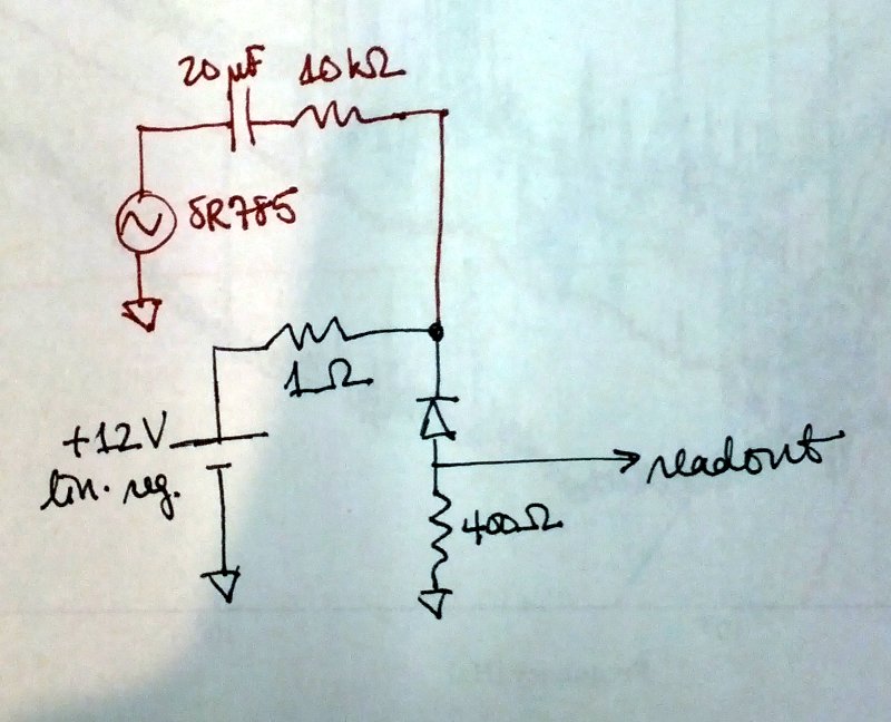
Each DCPD is biased with +12 V from a linear regulator with a 1 Ω output resistor. We wanted to inject extra bias noise, so we exposed the bias lines with a breakout board at the DCPD chassy in the HAM6 rack (see D1300502). Then we summed in the output of an SR785 across an impedance of 10 kΩ in series with 20 µF (see diagram; green shows the normal DCPD electronics and red shows the addition). The 10 kΩ gives a 1:104 ratio of bias fluctuation to drive voltage, and the capacitor ac-couples the drive so that it does not pull on the bias at dc.
With the SR875 we drove a 1 Vpk line first at 187.3 Hz and then at 62.4 Hz (i.e., the bias fluctuation was 70 µV rms). We looked at the response in DARM (at 2 W dc readout, with DARM still controlled by EX). We had 10 mA dc on each PD, in the 400 Ω transimpedance configuration.
For 187.3 Hz (from 02:03:00 to 05:22:00 Z), the magnitude in DARM was 1.13×10⁻¹⁸ m rms, which implies a coupling of 1.6×10⁻¹⁴ m/V. The noise of the regulator at this frequency was 0.9 µV/Hz1/2, which implies a DARM noise of 1.4×10⁻²⁰ m/Hz1/2.
For 62.4 Hz (from 05:33:00 to 05:56:30 Z), the magnitude in DARM was 1.4×10⁻¹⁸ m rms, which implies a coupling of 2.0×10⁻¹⁴ m/V. The noise of the regulator at this frequency was 1.9 µV/Hz1/2, which implies a DARM noise of 3.7×10⁻²⁰ m/Hz1/2. Note that there is some room for error here because the DARM control configuration here is not exactly the same as the low-noise configuration. However, the ugf and phase margin should not be too different in the two configurations.
This is very close to the current low-noise DARM noise floor. However, if DARM is limited by voltage noise of the regulators, we should either expect that the DCPD null stream is equal in magnitude to the DCPD sum (it isn't), or the regulator noises are coherent (they aren't).
I am not sure if there are any contradictions in these numbers. DARM calibration at DC is

C [W / m] = 4 * pi * G_arm / lambda * sqrt(G_prc * P_in * P_as / G_src) = 1.5e9 and 5e9 for input power 2W and 22W and 26mW at the AS port.

This means that the response you measured is ~2e-5 A/V. If the input power is 22W, 1uV/sqHz projects to 4e-21 m/sqHz around 100Hz. This number is what you have in your noise budget plots.
The freerunning DARM channel may not be properly calibrated in the low-power state with EX control, so the numbers I gave originally could be too high.
We directly measured 1.2×10⁻⁶ mA rms in DCPD B at 187.3 Hz, which implies a coupling of 0.017 mA/V, which implies the bias noise shows up in DCPD B at 1.5×10⁻⁸ mA/Hz1/2. The shot noise with 10 mA on the PD is 5.7×10⁻⁸ mA/Hz1/2. So it is a factor of 4 or so below the DARM shot noise, assuming DCPD A is similar. That's close to the dark noise, but the dark noise is flat down to a few tens of hertz while the regulator noise has some negative slope.
Voltage noise of bias (pin #8 of the d-sub), measured with BNC clip doodle and SR785 (with AC coupling).
Sheila, Rana
We continued the investigation. Today we hooked up a DAC channel to the bias to make sweeps and noise injection. No surprises relative to yesterday. Still seems so close to DARM as to be unbelievable. Maybe the 1 Ohm resistor in the bias circuit is not stuffed?
We also injected random noise into PZT2 to look for upconversion there. We saw the usual kinds of quadratic coupling; noise at a level ~500x above the quiesscent HVmon noise level was able to be just visible in DARM in the baseband as well as by injecting noise close to the 4100 Hz dither frequency.
0554 UTC, leaving it in 'low noise mode'. The BS coil driver is in some mixed low noise state giving us increased DAC noise below 50 Hz, but the noise above there is as good as ever.
Can't get the photodiode D's off the DCC at the moment (outage???), but surely there must be a biga$$ cap (ideally several in ||) from the pd cathode to ground??
Yes, in the in-vacuum preamp, there is a 1 uF capacitor from the Bias to ground. At the LM317T (voltage regulator that sets the bias), there is a 10 uF cap to ground, on the regulator side of the 1 ohm resistor (it's not shown in Rana's sketch above). In any case, the projection given above relies on the 1e4:1 scaling of the injected signal - can't you just measure directly the drive on the bias line, rather than assuming the 1e4:1 ratio?
Bigger caps are unlikely to help much. The noise is due to the internal burried zener diode which serves as the voltage reference. The BW of the regulator is about 10kHz here. A bigger C may reduce this, but may also increase gain peaking. Just use a low noise supply such as the one here. Noise performance: T1000025.
Den, Rana
We directly measured the voltage noise on pin8 and confirmed that our injection through the 9.09k resistor (not 10k as indicated above) scales as expected. It seems that the 1 Ohm resistor is really 1 Ohm (+/- 20%).
From MZ, we have http://www.edn.com/electrical-engineer-community/industry-blog/4422750/2/Simple-circuits-reduce-regulator-noise-floor.
This indicates that some larger caps may reduce the regulator output noise at 100 Hz by a factor of 5 or so. Could be easy to try if we have a spare whitening chassis sitting around.
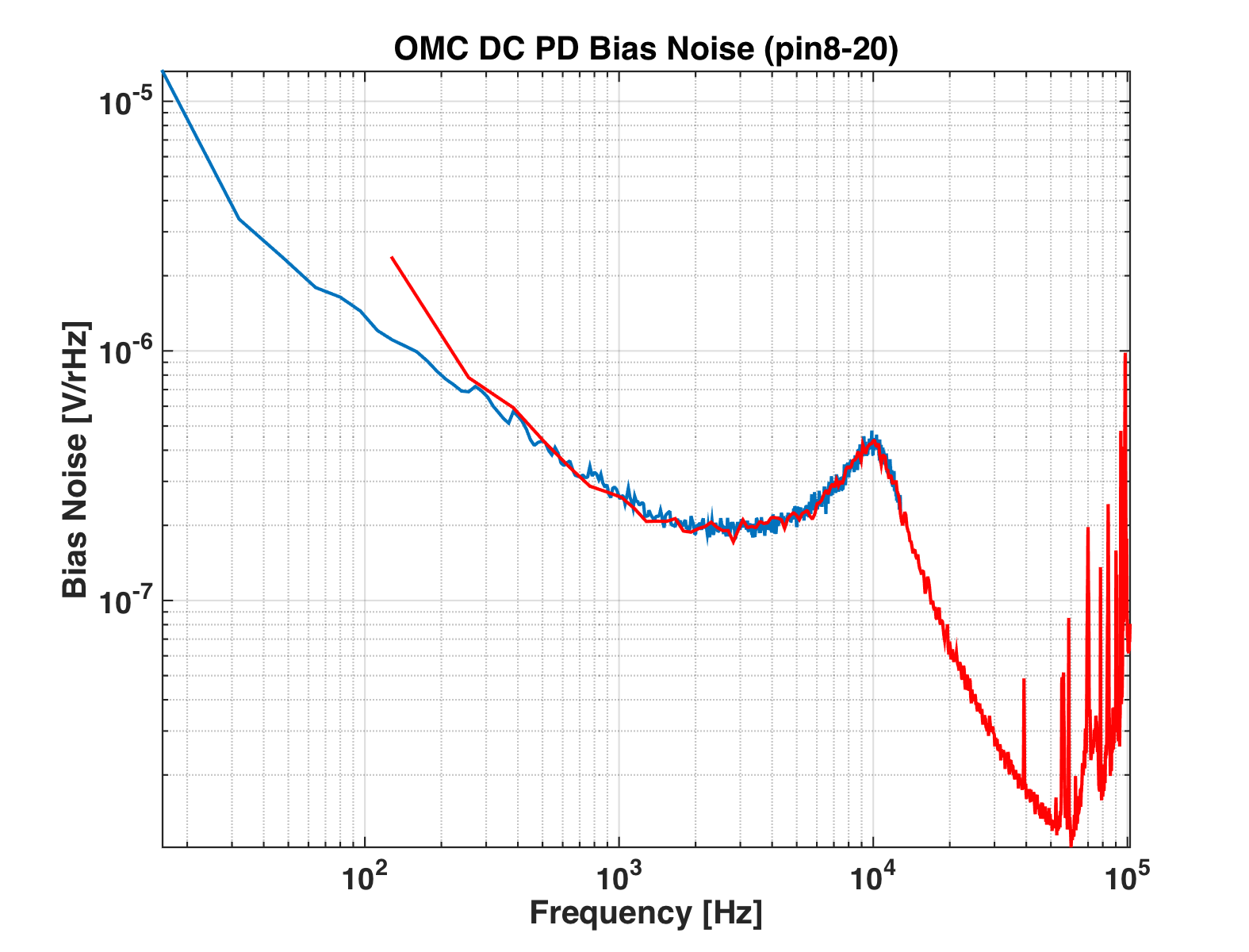
Rana, Sheila, Den

We have measured the bias noise with a better resolution and found that this noise is almost flat below 60Hz. Then made a projection of this noise to DARM when the input power was 22W and power on each OMC PD was 10mAmps. For PD A the coupling is 1.5e-15 m/V while for PD B is 3e-15 m/V. Attached plot shows the projection of bias noise to DARM. It is factor of ~4 below the current sensitivity.

According to the noise budget and measurement of the dark noise, this noise is above the dark noise level. This means that the noise is present only when the DC photocurrent is present.
Suggests QE compression due to bias reduction. For higher P it may be wise to not only improve bias voltage noise, but to fix anode-cathode potential. Either a true transimpedance
preamp, or a tracking supply at the rack.
We drove PD_B bias and measured the coupling of the bias noise to OMC NULL channel for different current levels. Plot is attached.

The coupling is close to zero when there is no power. The coupling scales linear for small currents and stays almost constant for large currents (>10mA on each diode).

We have also double checked that the optical signal scales linear with the current by driving an intensity line.
Kiwamu, Den

We have digitized bias channels (LSC:EXTRA_AI_2 channel) and double checked coupling to DARM. Attached plots show coupling of PD_B bias to DARM. There is a calibration line at 62.4Hz of this coupling.