aidan.brooks@LIGO.ORG - posted 10:14, Tuesday 08 March 2016 - last comment - 18:56, Tuesday 08 March 2016(25932)
Nominal TCS power levels for O2 - ITM substrate lens only
The attached plot (and script) shows the nominal TCS power levels required for O2 to correct for just the ITM substrate lenses.
The following values are assumed:
- ITMX substrate lens: -80km (single-pass)
- ITMY substrate lens: +590km (single-pass)
- Absorption: 250 +/- 50 ppb
- RH actuation: -9 uDiopters per Watt (single-pass)
- CO2 actuation: +62.3 uDiopters Per Watt (single-pass)
- Self heating: 487 uDiopters per Watt (single-pass)
- Nominal lens required in substrates: +50km (in front of ITM - see attached note from Chris)
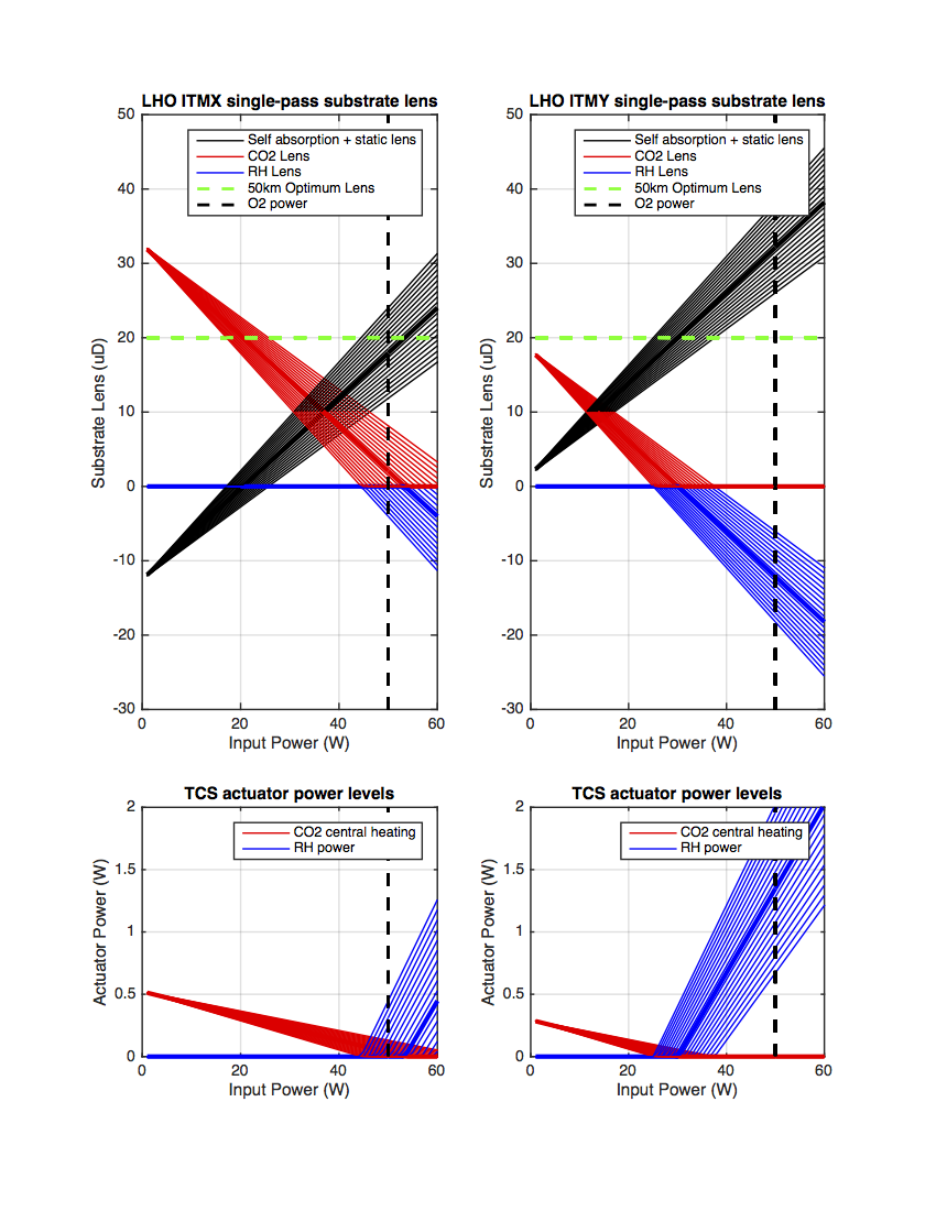
The bottom line is that we will cease to need central heating around 45W on ITMX and 30W on ITMY and will need to start using the RHs to compensate for the thermal lenses. No consideration is yet given to HOM correction with annular CO2 heating.
Subject: Re: RC as-built designDate: May 14, 2015 at 7:54:37 PM EDT
Hi All,
The value of the thermal lens that was always used when adjusting the cavities is 50 km.
The issue which caused all of the confusion last summer was one of definition; i.e. what does it mean to have a 50 km thermal lens. The plots Muzammil put together, on which the decision to include the thermal lens was based, modeled the thermal lens as being inside the ITM. The model we used to adjust the optic positions had the 50 km thermal lens immediately in front of the ITM. The effective focal length in the two cases differs by a factor of n (the index of refraction), with it being stronger in the model which was used to calculate the positions. Because of this the positions were tuned to have a slightly stronger thermal lens than was originally decided on based on Muzammil's plots.
Fortunately, Lisa and I discovered that this is essentially a non-issue since the length changes needed to tune for the two different thermal lenses are less than the length changes needed to compensate for tolerances in the measured radii of curvature of the optics.
Images attached to this report
Non-image files attached to this report


Comments related to this report
Thank you Aidan for working on this.
Speaking of the thermal lensing, we (the LHO crews) have been discussing a possible TCS pre-loading strategy. Here are some summary points of our (future) strategy:
-
We dial the ITMY ring heater to the value that is optimized for 50 W PSL power. According to your plot, a ring heater power of 1.3 W seems the optimum.
- We let it stay there all the time regardless of whether the interferometer is locked or not.
- We do this because the ring heater can be too slow to keep up with the interferometer's thermal state
-
On the other hand, we do not heat up the ITMX ring heater (at least at the beginning of the test).
- Perhaps we will perform a fine adjustment later with the fully locked interferometer with 50 W input.
-
Before the interferometer is locked, we engage both CO2 lasers to pre-heat the interferometer.
- CO2X will be at 0.5 W according to your plot
- CO2Y will be at 0.3 W according to your plot
-
Once the interferometer is locked and starts powering up, we turn off the CO2 lasers.
- For the early phase, we are thinking of a simple power down with a step function.
- As a next step, we will attempt transient compensation by applying pre-calculated CO2 requested power.
- Cao has already looked into this transient compensation issue and had a matlab code ready to calculate various configurations.
-
We can play with the ETM ring heaters to see if we can maneuver away from the parametric instabilities.
- I have not done any calculation for this yet.
- As soon as the interferometer is unlocked, we set the CO2 back to the pre-heat settings in order not to cool down the interferometer.
Any comments/questions are welcome.