[Kiwamu, AIdan, Elli, Cao]
Following from alog 25905, we attempted to realign the beam spot, which is suspected to be the beam reflected from the HR surface of ITMY onto Hartmann sensor. In order to do this:
1. Turn off CAGE SERVO, misalign the SR3 to the PITCH and YAW values:
PITCH: 1458
YAW: -216.9
2. Since this beam is most far off from the nominal values in PITCH, we start walking the SR3 PITCH back to the nominal value (563.4. At the nominal value, a beam is centered onto HWS, which we suspected it to be the one refleced from AR surface). The walking is done in in increment:
- Decrease the PITCH of SR3 until the beam of interest moves up sightly off the amera active surface.
- Start decreasing the PITCH of the upper periscope, then decrease the PITCH of the lower periscope to compensate. This essentially translate the beam upward, bringing the beam of interest back down into the image frame of HWS.
3. After moving 400 radians in PITCH closer to nominal value, the SLED beam was clipped on the upper periscope mirror (2'' mirror). Initially prior to adjusting the periscope mirror, the beam was at the center. Therefore, a change in 1/sqrt(2) inch helps achieving a change of 400 rad in PITCH. At this point, the green beam in also close to upper edge of th upper periscope mirror. We then moved the upper periscope upward by 0.7 inch order to accomodate another 400 rad change in PITCH of SR3 to move closer to nominal value.
4. After reposition upper periscope mirror, we repeated the similar process of walking SR3 back to nominal values and tilting the upper periscope mirror. However, once achieving SR3 PITCH of 880, we started seeing clipping. Using IR viewer to look into the viewport, Kiwamu identified that the the beam is cipping on the top edge of the in vacuum lens (which was also the wong lens installed). We noticed that the green beam was at the bottom of the upper periscope mirror. We wondered if there was any separation between SLED beam and the green beam of the case of ITMY HWS, considering the y beams pass through SR2 and a wrong in-vacuum lens. We will need to check with Aidan for some ray-tracing model to investigate this.
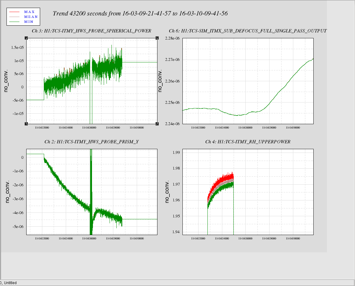
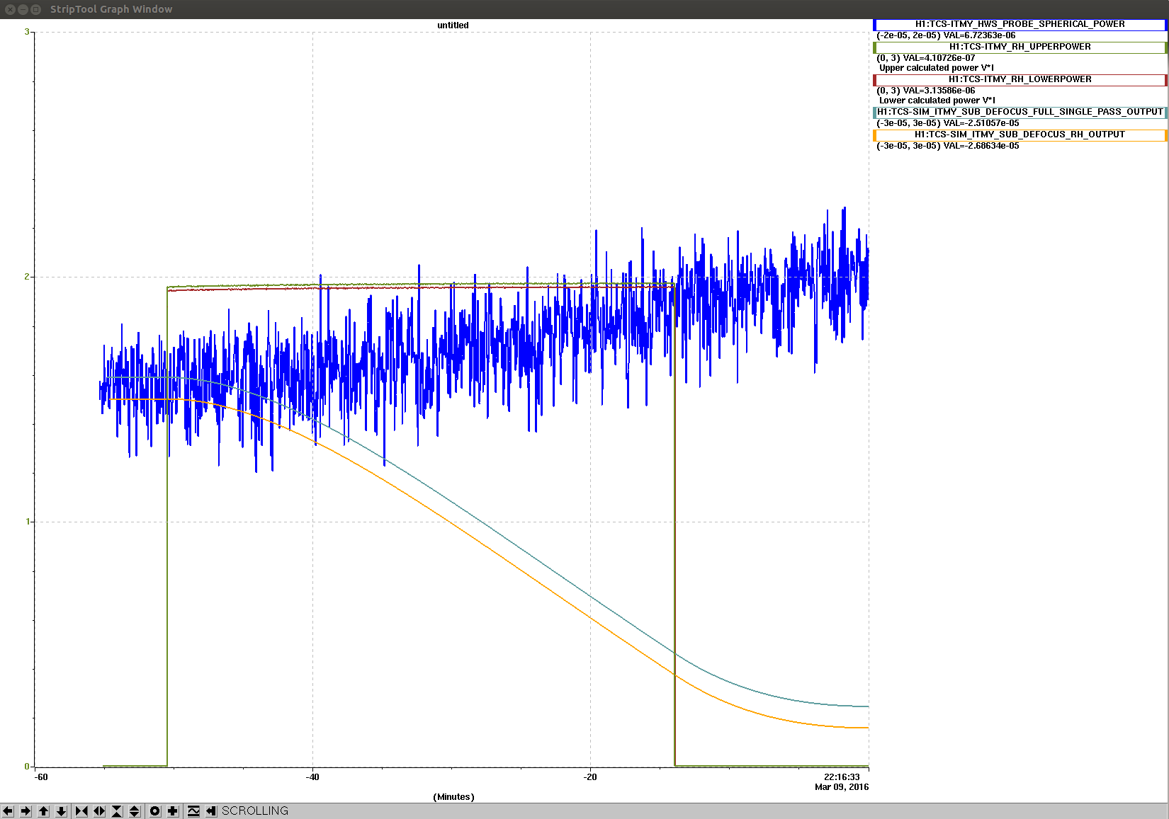
5. Due to this clipping,we could not proceed walking the desired beam onto HWS at SR3 nominal PITCH and YAW values. We then moved the upper periscope downward to initial position, misalign SR3 such that the HR beam candidate was centered onto the HWS and started the ring heater test. Each RH segment were turned on to 2W and we observed the measured spherical power from the HWS, compared to the simulation. This was indeed the first beam that we observed changes when RH is applied. However, looking at image RH_ITMY_9Mar.png , we noticed the trend of change did not follow what we expected from the simuation:
i. When RH is on,we expected the spherical power to decrease, what observed was the opposite in which the spherical power measured increased with time.
ii. The rate of increase in spherical power was much lower than the simulated rate of decrease. Whereas in my recent study of the RH model for X-arm, the magnitude of spherical power simulated is much smaller than measured data.
iii. The measurement of spherical power was very noisy.
For the first two points, I suspected it's either:
1/ The beam may not be centerd on the test mass but off slightly to one side and what we're getting is an artefact .
2/ The magnification and the change to a concave lens (the wrong in-vaccuum lens) have not been accounted for correctly, thus resulting in a flip of wavefront, giving rise to increase in spherical power measured.
Either way, I will have a look at the gradient plot tomorrow and see if we can do some ray tracing modelling to identify where the problem comes from.
The attached shows a cartoon of what we think the situation is.
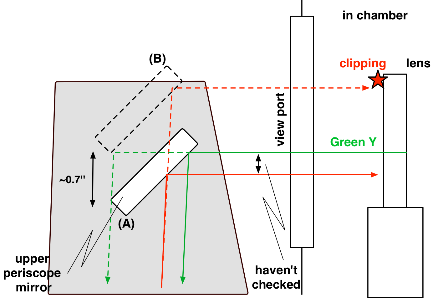
As Cao explained in his alog, we needed to shift the upper periscope mirror in order to get the beam of interest aligned on HWS with the nominal SR3 alignment. Position (A) is the nominal location of the upper periscope mirror in which a wrong beam has been aligned to HWS (alog 25905). Position (B) is a place we tentatively shifted the mirror position. According to the screw holes on the periscope, we seem to have shifted the mirror and its base plate by 0.7'' upward. A back-of-envelope calculation suggested that the mirror needed to go another 0.7'', but we stopped at this point because we started having an issue.
In position (B) the beam started clipping at an in-vac lens in the HAM4 chamber. This is consistent with what we saw previously (alog 25766 although no mention in the log). The clipping was visible through the viewport with an IR viewer, and also visible on the SR3 camera that clearly showed a clipped beam incident on SR3. Interestingly, the green beam started falling off the upper periscope mirror at the bottom of the mirror. It completely missed the bottom periscope mirror.
After today's alignment challenge and test, we shifted the mirror back to position (A) so that we can have beams which are not clipped.
SR3 was left misaligned by 771 urad in pitch overnight. I re-engaged the SR3 cage servo and noticed that the output was very large. Since Team TCS had been moving it around last night, I trended the Optic_Align values, and put them back to their positions from early yesterday. Yaw was at its nominal position, but pitch was too high by 771 urad.
I looked further into the data from last night RH test of the ITMY HWS. We were misalining the SR3, to test whether the [1458, -216.9] beam the HR beam:
The time series seen from dataviewer DV_RH_IMY_9Mar.png shows that together with the small change in spherical power, there is also a change strong change in prism.
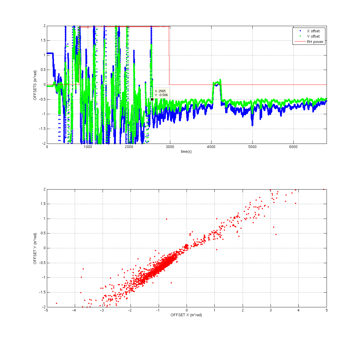
The ratio between spehrical power and prism results should give the offset of the beam from the test mass. Therefore, I looked at the ratio between PRISM_X/SPHERICAL_POWER and PRISM_Y/SPHERICAL_POWER.
Image OFFSET_RH_9Mar.png shows the plot of the time series of these two ratio and the second subplot shows the PRISM_X/SPHERICAL_POWER vs PRISM_Y/SPHERICAL_POWER.
The ratios look very noisy for the first 40 minutes that the HWS was running, and us independent of the power applie onto the RH. But we can see a trencd that both ratios decreases to -1 m*rad. This shift to the offset at -1 m*rad can be seen quite clearly in the second subplot where there is a cluster of data point at (-1,-1) region.
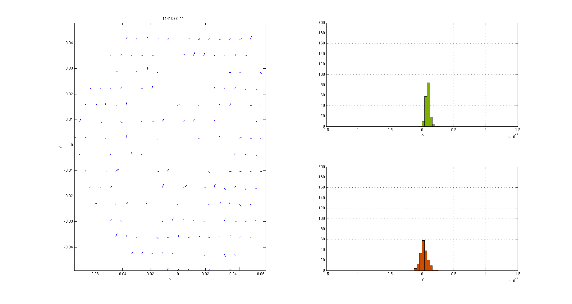
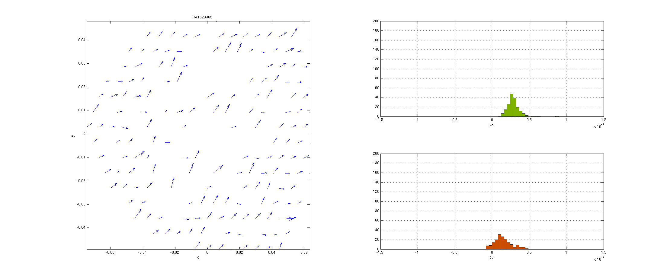
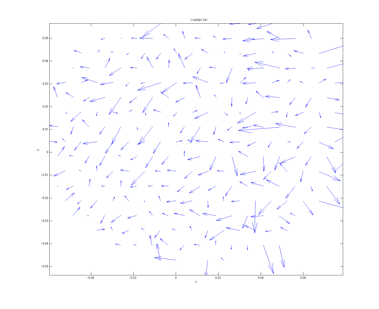
Gradient plot showed strong prism developing but no evidence of spherical power (compare beginning frame RH_ITMY_grad_start.png and final frame RH_ITMY_grad_end.png). What was more curious was that some centroids were missing from the gradient plot (see RH_ITMY_grad_end.png ).This certainly has effected the fidelity of any parameter measured by the HWS. Howevwe there is certainly no evidence supporting this is the right spot.
Aidan has recently checked the reflectivity of AR and HR surface, and for this wavelength (840 nm), the AR surface has the stronger reflectivity. Thus now the suspected HR beam is the one we are currently centered on at the nominal values PITCH and YAW of SR3. We have now turned the both ITMX and ITMY HWS on (alog 25991).
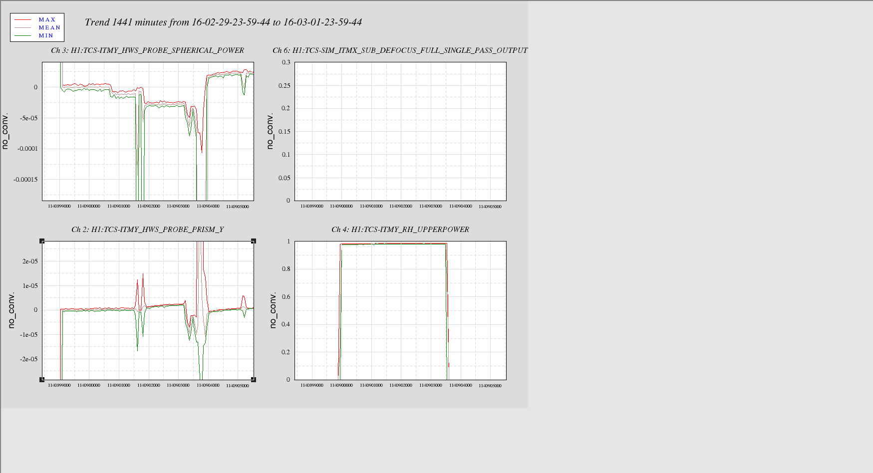
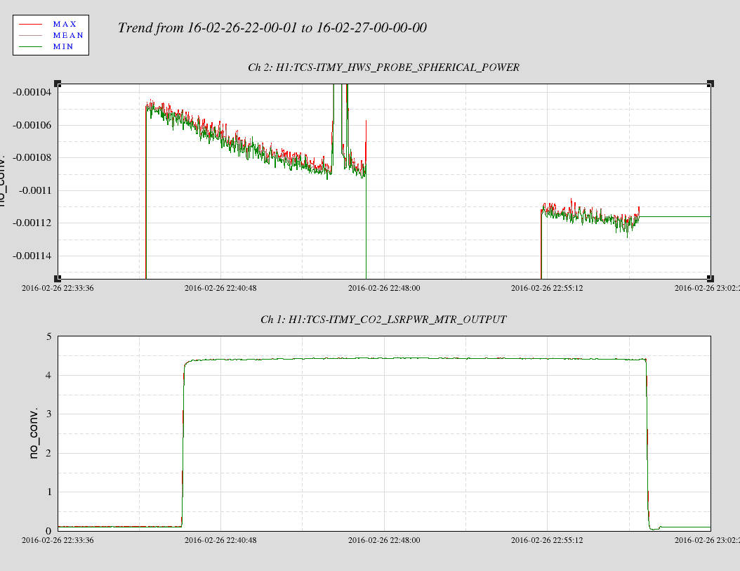
However our previous test (RH and CO2 laser) with this spot also results in strange result that did not support our simulation. For example, time series RH_ITMY_1Mar.png shown for RH test on March 1 when this beam was centered on HWSY showed that there was no change in spherical power while RH was turned on to 1W for 1 hours. The step change observed was resulted from us opening the HWS table to replace HWSX SLED on the day (alog 25806). The CO2 test data on 26 Feb with the same beam showed a decrease in spherical power measured, whereas the simulation expected spherical power to inrease (see ITMY_CO2_26Feb.png). Checking the gradient plot also did not show evidence of thermal lensing expected with CO2 but gradient developing towards the (-ve x, -ve y) region of the quiver plot.