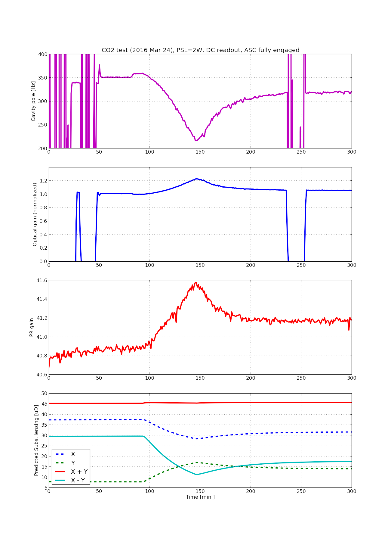
Preliminary conclusion: the DARM cavity pole seems to be a strong function of the differential lensing. I was able to change it from 357 Hz to 220 Hz (!!!)
I will post more details tomorrow.
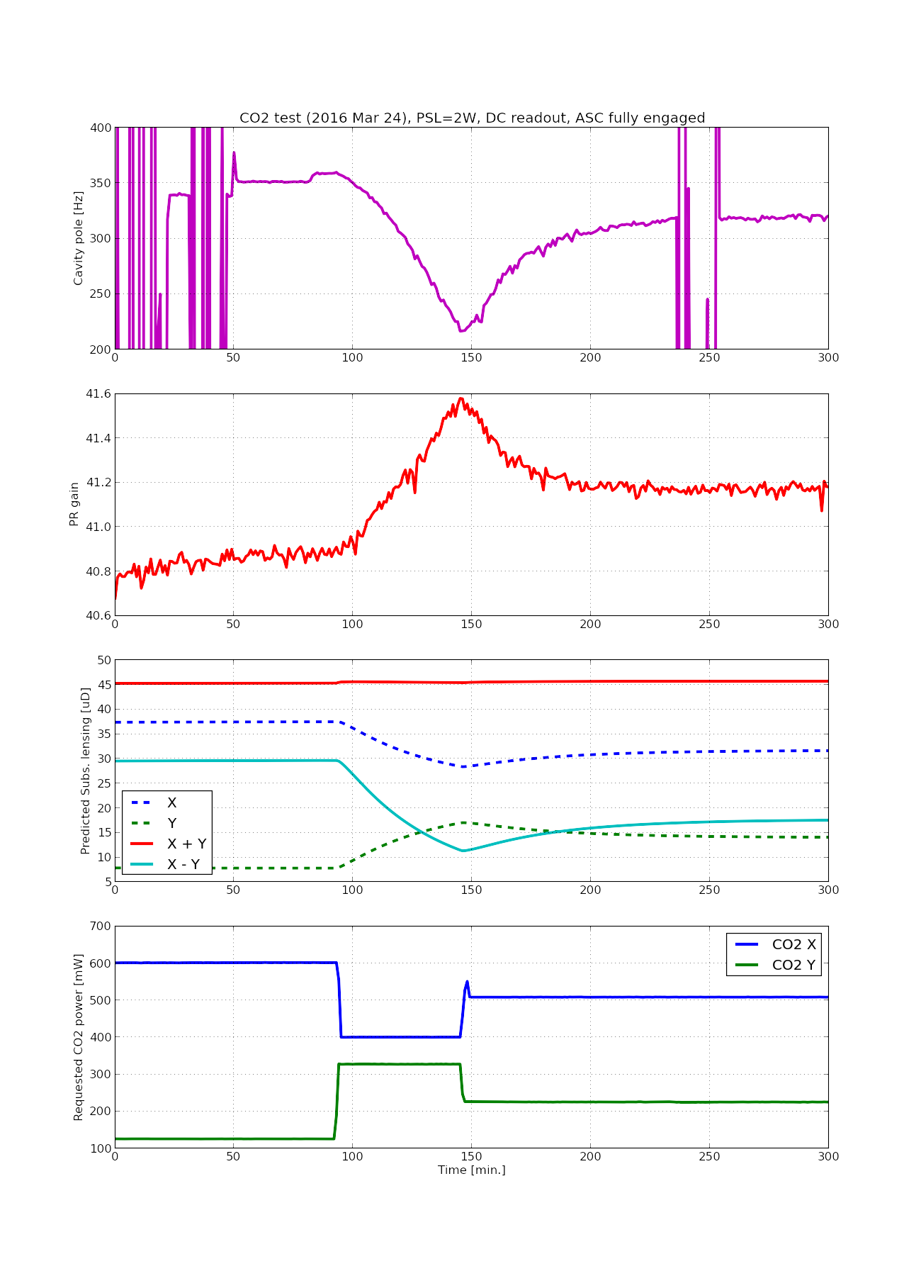
The cavity pole measurement is not valid until t=80 min. and also in the time band approximately between 230 and 250 min. The interferometer was locked on the DC readout with ASC fully engaged, The PSL power stayed at 2 W throughout the measurement.
Learning this behavior, I would like to do the followings in the next test:
- Go further to the positive side of the differential lensing (ITMX's lensing goes larger than ITMY) to see if we can recover a high cavity pole.
- Search for optimum points for frequency and intensity noise couplings.
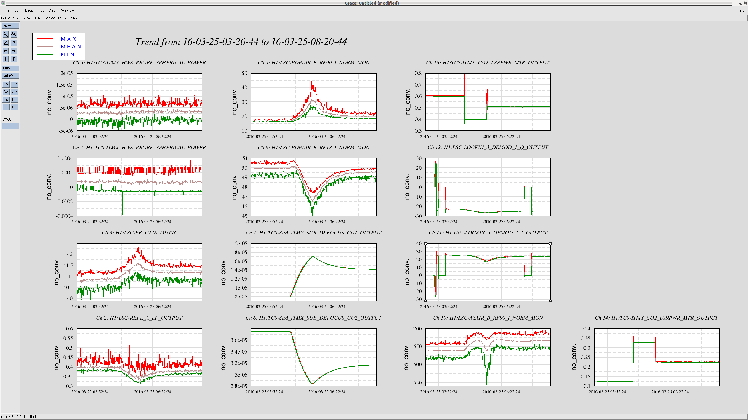
By the way the second attachment is trend of various channels during the test.
Actually, Hang pointed out that SRM and SR2 showed much more visible reactions in their alignment. See the attached.
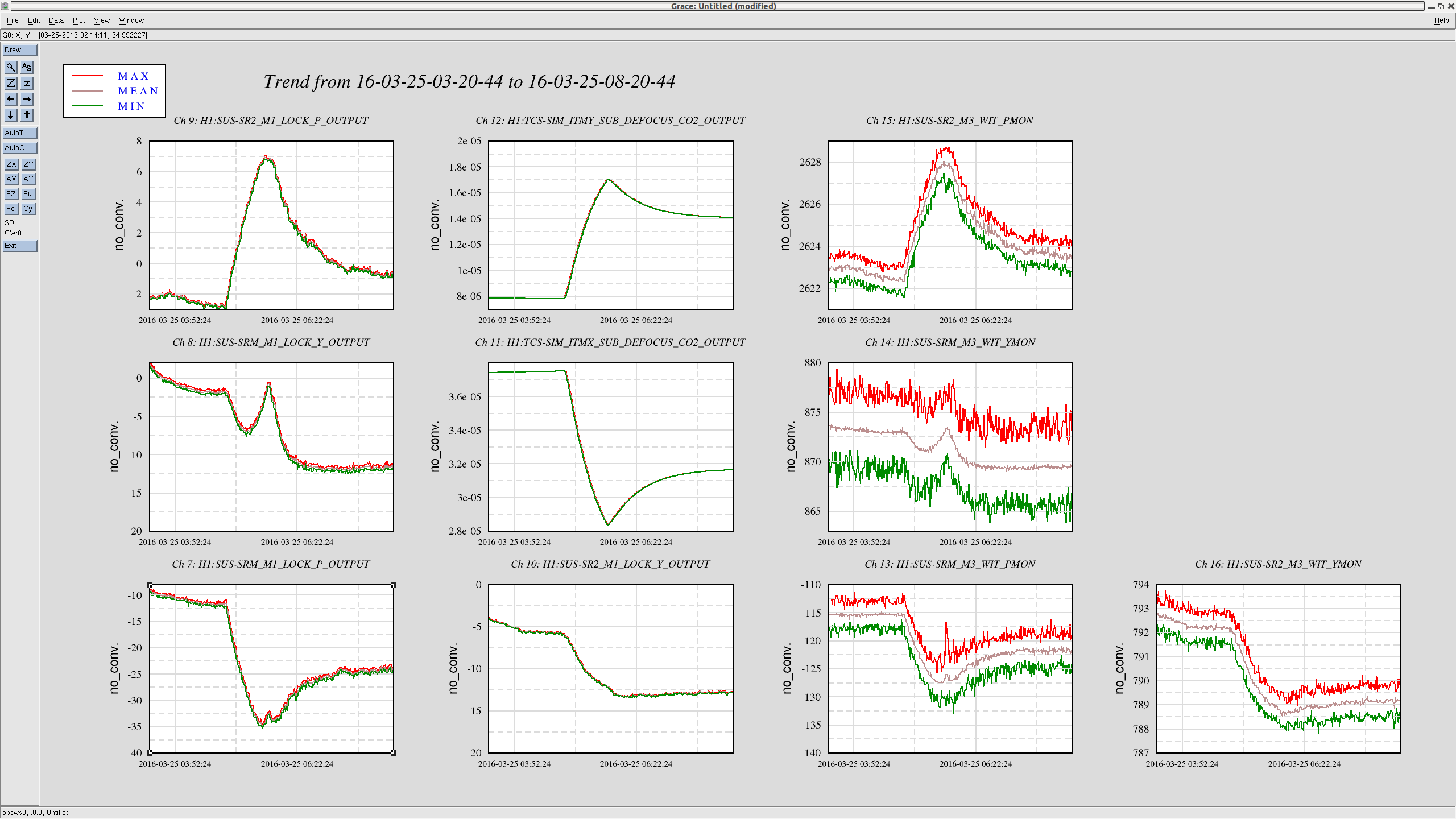
In particular, SR2 pitch seems to trace the lensing curve.
Also, looking at PRM and PR2, we did not see drift or anything interesting.
A simulation with substrate lensings as reported in the elog did not show a large variation of the cavity pole: about 1% or so. My suspect is that the change in differential lensing is causing the IFO working point to change: alignment or longitudinal offsets? In my simulation the longitudinal working point is obtained from simulated error signals, so I don't see any offset in the locking error signals.
The differential lens change is about 18 microdiopters. For what it's worth, there is ~2.3% of power scattered from the TEM00 mode on a double-pass through such a lens. Whether such a purely differential lens in the SRC would manifest solely as a 2.3% round-trip loss in the differential TEM00 mode of the arms is questionable. I still need to run the numbers for the effect on the DARM cavity pole if we simply added this loss to the SRM mirror.
Here are some more small points to note.
[Two cavity pole measurements]
At the beginning of the run before I started changing the CO2 power, I ran a Pcal swept sine measurement in order to get the cavity pole frequency. The DARM open loop was also measured within 10 minutes or so in order for us to be able to take out the loop suppression. In addition, I ran another pair of Pcal and DARM open loop measurements to double check the measurement. The attached below shows the transfer functions with fitting. The fitting was done with some weighted least square algorithm using LISO.
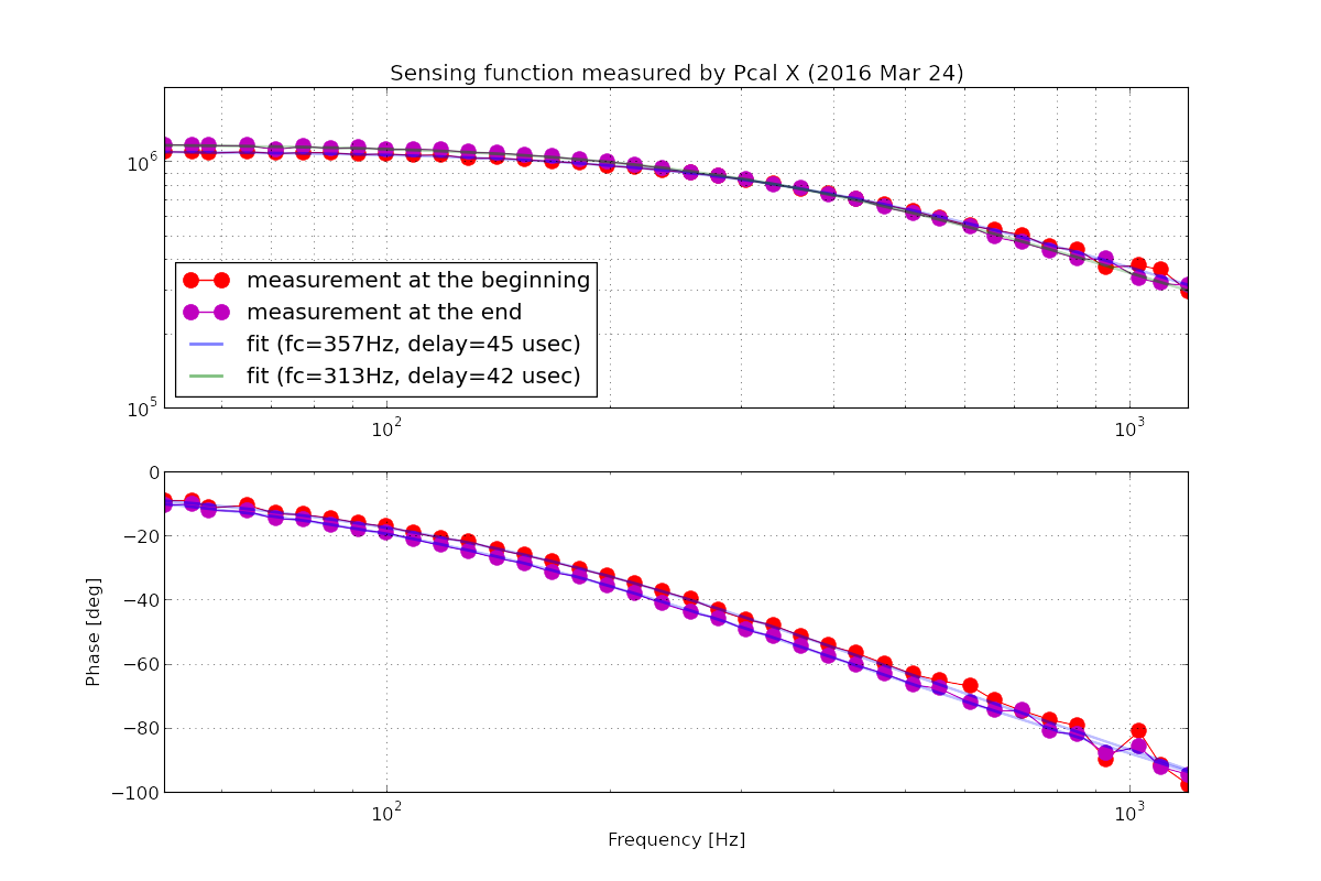
As shown in the plot, the shift in cavity pole is obvious. Also the optical gain is different between the two measurements.
[Evolution of the sensing function throughout the test]
The optical gain and cavity pole are negatively-correlated. The trend of the optical gain looks very similar to the one for the power recycling gain, but the variation in the optical is much larger-- the optical gain increased by 20 % at most relative to the beginning. As pointed out by Valera in the ISC call today, a fraction of the variation in the optical gain could be due to the OMC mode matching.
[Alignment drift]
As Gabriele pointed out in the comment, it may be possible that the CO2 lasers affected the alignment of the interferometer and changed the amount of losses in some parts of the interferometer or introduced some other impact on the cavity pole. Hang and I have looked at trend of optical levers during the time.
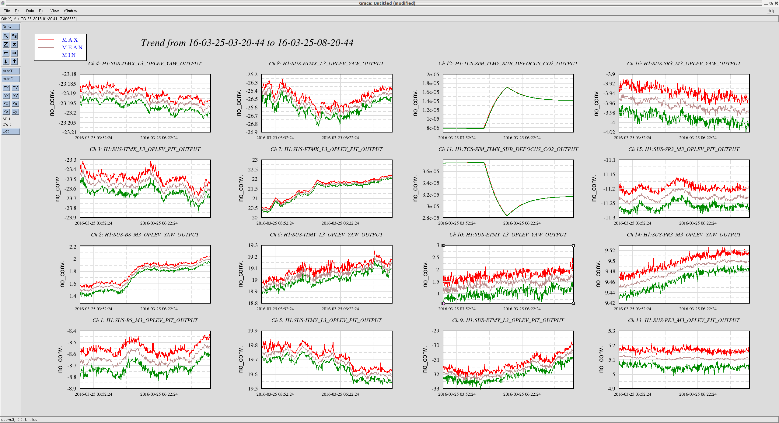
There are two optics that seemingly reacted to the differential lensing, that are BS yaw and ETMX PIT. The showed a kink point at the time when the CO2 power changed. In addition, ETMY pit slowly drifted by 2 urad and ETMY yaw moved by 1-ish urad. Other large optics also moved but were within 1 urad. From a naive point of view, the alignment does seem to explain the behavior of the cavity pole going down and up during the measurement because none of them clearly showed a going-up-and-down type behavior. However, it is possible that the true misalignment was covered by drift of the oplev itself.
[Online cavity pole measurement]
The cavity pole was measured by injecting a line at 331.9 Hz at the DARM output. The DARM loop is notched out at the same frequency. The measurement method is described in 18436.
Some simulations I did months ago for the MIT commissioning meeting (https://dcc.ligo.org/LIGO-G1500593) showed that the cavity pole is very sensitive to SRC matching. I therefore expect the cavity pole to be also very sensitive to SRC alignment, as seems to be sugegsted by the SR* mirror drifts.