Daniel, Ed D., Ross, Dave B., Terra
In anticipation of more parametric instabilities as we go to higher power, we've set up the ESD PI damping scheme here (which has been successfully used at LLO so far).
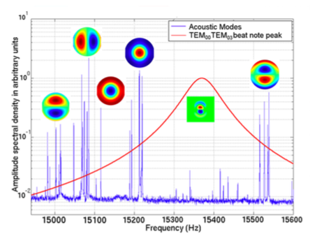
Brief context: Figure below shows example relationship between blue mechanical modes of test masses and red optical TEM00 and TEM03 beat note peak (seen at LLO during O1; figure courtesy of Carl Blair). As red optical beat note peak moves left or right, it overlaps with the mechanical mode groups on either side, which can lead to PI. Each mode group has 4 peaks, one for each test mass. Simulations of surface deformations for each mode are shown near their respective peaks. Previously at LHO, PI was observed near 15540Hz and the ETMX ring heater was turned on, effectively moving the red peak leftward away from the 15540 mode group and towards the stable region as shown below. However, as we increase power, high mechanical mode density will mean smaller stable regions to tune towards; hence the need for an active damping scheme.
Work this past week: ESD damping scheme is set up and ready for testing.
We've updated end station pi models (h1susetmxpi, h1susetmypi) and added a corner station pi model (h1susitmpi) to allow for ESD driving; these now match LLO's PI models, with some extra downconversion options added. Note that LHO currently doesn't have ITM ESD drivers, so corner station model is just in anticipation.
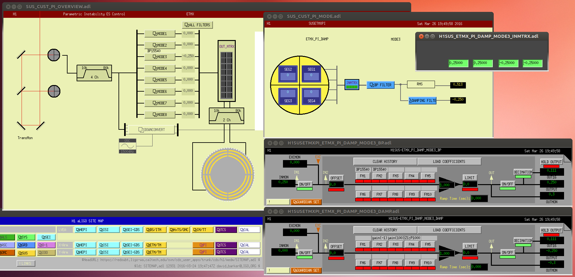
I've overhauled the X and Y-arm PI medm screens (screenshot attached), located in userapps under /sus/common/medm/pi. For now, only X and Y arm PI screens exist - orange PI buttons on main sitemap. Screens shown in screenshot unfold clockwise from top left for ETMX. Main screen holds list of modes that will be identified over time. Each mode then has its own screen for it's damping parameters.
The basic damping scheme for the ETMs is as follows: Arm transmission QPD signal carries test mass resonant mode information. QPD signal is passed through an analog 10K - 80K filter (see D1400419 for a rather enlightening PI hardware diagram). The 4-segment QPD vector is multiplied by INMTRX which selects for vertical or horizontal mode orientation. Band pass filter bank to pick out mode frequency; usually 2 x tight bandpass of <10Hz. Control filter bank to damp; gain of 100+, gain of -1 to damp, double zero1, pole 1000. All are shown in attached medm screenshot. Finally, PI has actuation control on two LNLV ESD drive segments: UR & LL.
We're also temporarily recording the OMC DP PDs at 64K at H1:OMC-PI_DCPD_64KHZ_A and _B as these have the best SNR for PI modes (via the new h1omcpi model). After the ring heater test (discussed below), we'll change these to record at a slower rate.
To do: There wasn't an available long lock > 10W while I was here so there's some testing of the system still to do.
1. Test ESD damping on known mode: As mentioned above, PI was previously seen at LHO at 15540Hz in ETMX at 15W. It was successfully avoided by turning the ETMX ring heater on; it has remained on since then at 0.5W requested power upper and lower. In an upcoming longer lock at ~15 W, the ring heater should be turned off to allow the 15540 mode to ring up and attempt to be damped with the new ESD scheme.
2. Ring heater test: To match mode to test mass, we can step up the ring heater on each respective test mass and watch which PI mode shifts in response. We need to step up one ring heater at a time by 0.1 W (both top and bottom simultateously) for 10-15 minutes each.
3. Implement line tracker before damping filter: Ed and Ross have been working on a line tracker that will lock onto each somewhat-well-identified PI mode. It's in the last stages of testing and will be added to the model and sitemap (in between the BP filter and damping filter) asap. Ed & Ross have a more detailed alog about this in the works.
The response of the TM ROC is given in the TCS SIMULATION. (For ETMX, for examplel, H1:TCS-SIM_ETMX_SURF_DEFOCUS_RH_OUTPUT and the full ROC is in H1:TCS-SIM_ETMX_SURF_ROC_FULL_OUTPUT).
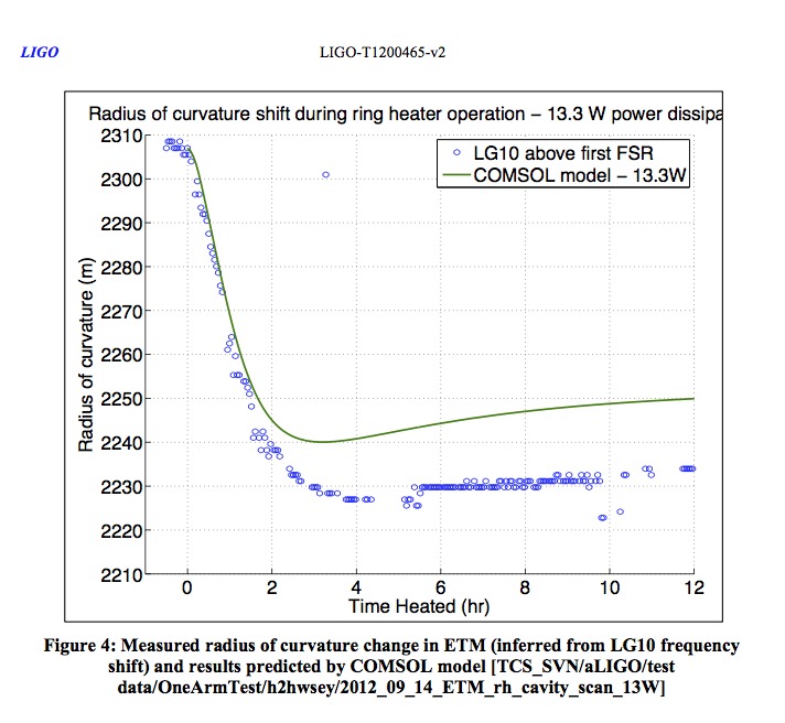
We measured the response of the ROC to the RH back in the One Arm Test. See page 9 of T1200465.