We've had much more success tonight with the non-broken Xarm Trans QPD. We once again re-centered the spots on the ETMs, although they didn't need much moving. We are able to sit at 10W and 12W just fine now. Now, we're running into regular ol' loop oscillations, so we've been measuring loops at different powers, and trying to re-tune them.
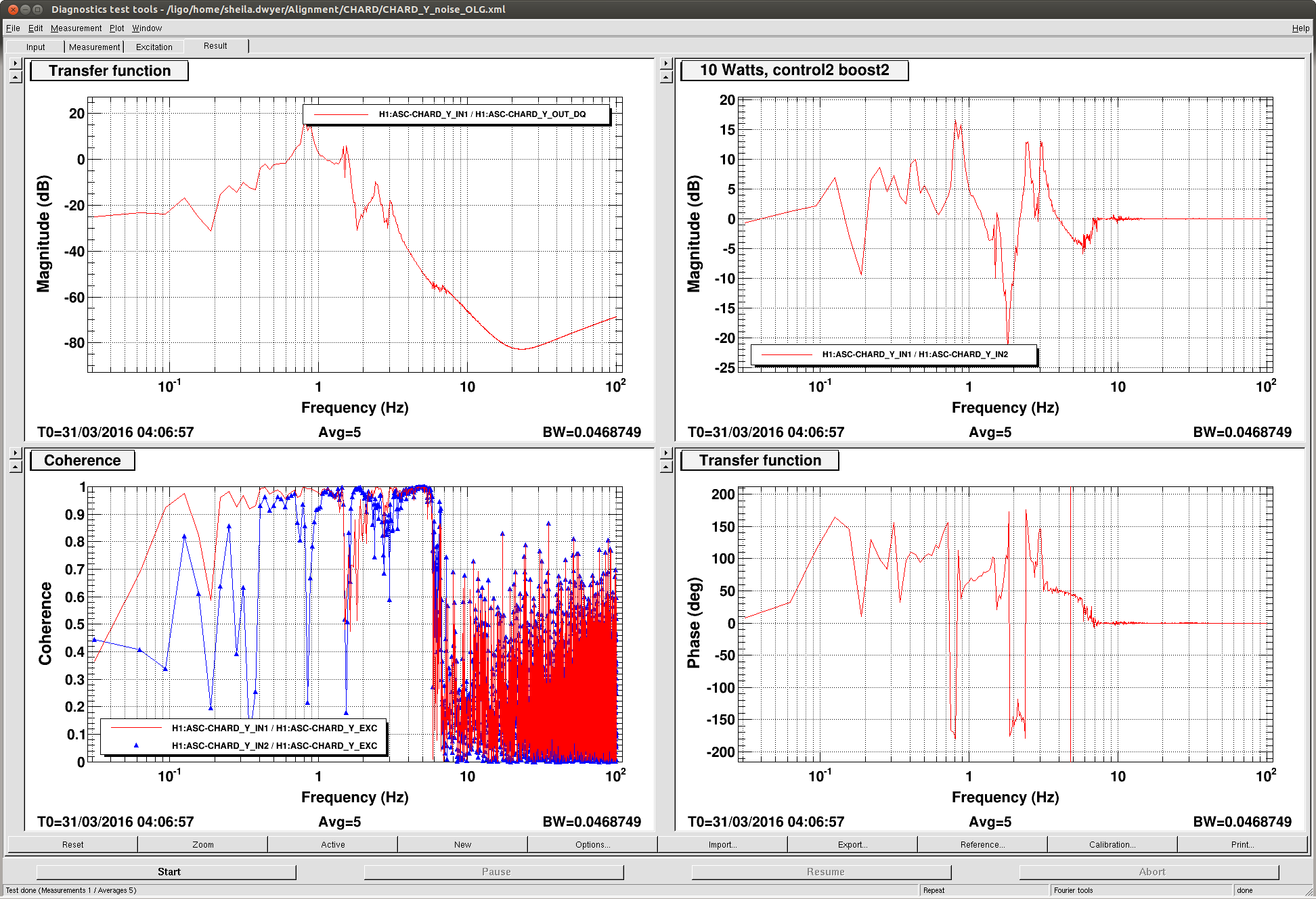
CHARD Y seemed the most egregious, so we created a new control and boost filter combo, which live in FMs 4 and 5. Unfortunately, these filters are totally unuseable at 2W, although they improve our stability at 10W, so right now the guardian still only engages the old loop shape filters. We'll have to re-think the 2W filter situation to make sure we can transition between these filters. Right now, we were by-hand turning off the CHARDY loop, changing the filters, then re-engaging the loop. Attached is an open loop gain for the new loop.
PRC2 pitch we've decided is kind of okay if we use a factor of 2 less gain.
Now, we're seeing oscillations that also show up in AS 90, so we suspect either the MICH or SRC angular loops. Unfortunately, there's something going on with NDS/the lockloss plotter/something, such that I can't get data from the last ~5 locklosses. The ones before that, I can still get and plot, but it can't find data for the last several even if it's been an hour since that lockloss.
So, next up: Measure the MICH and SRC loops at 10W to see if they're close to unstable. Measure again at 15W, and then think about going from there.
I feel I should know this already, but what is known about the QPD failure (circumstance at failure, failure mode, etc.)
It's not totally clear to me yet what the exact problem was. R.McCarthy is looking into why (apparently) putting the PI chassis spoiled the signal. Removing the new PI chassis seems to have fixed our problems. See alog 26328 and comments for symptoms and Rich's comment.
The PI AA was off and its OpAmp inputs were probably 'shorted' to ground due to the input protection diodes.
I am designing the input circuitry for the ITM PI Driver using the same input chip as that used on the ETM PI AA, so I will hedge our bets by including some input protection circuitry (current limit and clamp) to avoid this if that turns out to be the case.
In the lab, Fil reproduced the situation at EX by connecting a function generator to a coil driver test box (D1000931) and only used the single to differential converter of the board inside (D1000879) to drive the input of unpowered PI bandpass, and daisy chained to powered AA board.
Things looked OK until the PI input reached about +-1V differential (that's +-500mV positive and -+500mV negative), anything larger than that and the voltage started to be pulled down. Looked like a diode and a small resistor in series to me. As soon as the PI bandpass was powered on, everything got back to normal.
Daniel is correct.  The chips used on the input to the PI filters have internal input protection diodes that will (up to the limit of their current handling capacity, which is not much over 10mA or so) clamp the voltage from the QPD amplifier to something around a volt.

This is not a problem if the PI BPF is powered, which is the normal state of the system.  This event prompted a redesign of the differential input to the ITM ESD Driver to avoid this in the future.  Another case of incremental learning.