I did some follow-up tests today to understand the behavior of the DARM cavity pole. I put an offset in some ASC error points to see how they affect the DARM cavity pole without changing the CO2 settings.
I conlude that the SRC1 ASC loop is nominally locked on a non-optimal point (when PSL is 2 W) and it can easily and drastically changes the cavity pole. The highest cavity pole I could get today was 362 +/- a few Hz by manually optimizing the SRC alignment.
[The tests]
This time I did not change the TCS CO2 settings at all. In order to make a fair comparison against the past TCS measurements (26264, 26245), I let the PSL stay at 2 W. The interferometer was fully locked with the DC readout, and the ASC loops were all engaged. The TCS settings are as follows, TCSX = 350 mW, TCSY = 100 mW. I put an offset in the error point of each of some ASC loops at a time. I did so for SRC1, SRC2, CSOFT, DSOFT and PRC1. Additionally, I have moved around IM3 and SR3 which were not under control of ASC. All the tests are for the PIT degrees of freedom and I did not do for the YAWs. During the tests, I had an excitation line on the ETMX suspension at 331.9 Hz with a notch in the DARM loop in order to monitor the cavity pole. Before any of the tests, the DARM cavity pole was confirmed to be at 338 Hz by running a Pcal swept sine measurement.
The results are summarized below:
- SRC1, offset = from +400 to -300 cnts, cavity pole = from 350 Hz to 275 Hz
- SRC2 , offset = from +0.2 to -0.2 cnts, no change
- DSOFT, offset = from -0.03 to 0.03 cnts, no change in cavity pole, but a noticeable drop in the power recycling gain (41 --> 39).
- CSOFT, offset = from -0.03 to 0.03 cnts, no change in cavity pole, but a noticeable drop in the power recycling gain (41 --> 38-ish).
- PRC1, offset = from -0.1 to 0.1 cnts, no change in cavity pole, but a noticeable drop in the power recycling gain (41 --> 38-ish).
- IM2, some large offset, no change in cavity pole.
- SR3, offset = +/- 50 urad, no change in cavity pole or recycling gain.
The QPD loops -- namely CSOFT, DSOFT, PRC1 and SRC2 loops -- showed almost no impact on the cavity pole. The SOFTs and PRC1 tended to quickly degrade the power recycling gain rather than the cavity pole. I then further investigated SRC1 as written below.
[Optimizing SRC alignment]
I then focused on SRC1 which controlled SRM using AS36. I switched off the SRC1 servo and started manually aligning it in order to maximize the cavity pole. By touching PIT and YAW by roughly 10 urads for both, I was able to reach a cavity pole of 362 Hz. As I aligned it by hand, I saw POP90 decreasing and POP18 increasing as expected -- these indicate a better alignment of SRC. However, strangely AS90 dropped a little bit by a few %. I don't know why. At the same time, I saw the fluctuation of POP90 became smaller on the StrioTool in the middle screen on control room's wall.
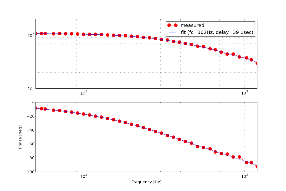
In order to double check the measured cavity pole from the excitation line, I ran another Pcal swept sine measurement. I confirmed that the DARM cavity pole was indeed at 362 Hz. The attached is the measured DARM sensing function with the loop suppression taken out. The unit of the magnitude is in [cnts @ DARM IN1 / meters]. I used liso to fit the measurement as usual using a weighted least square method.
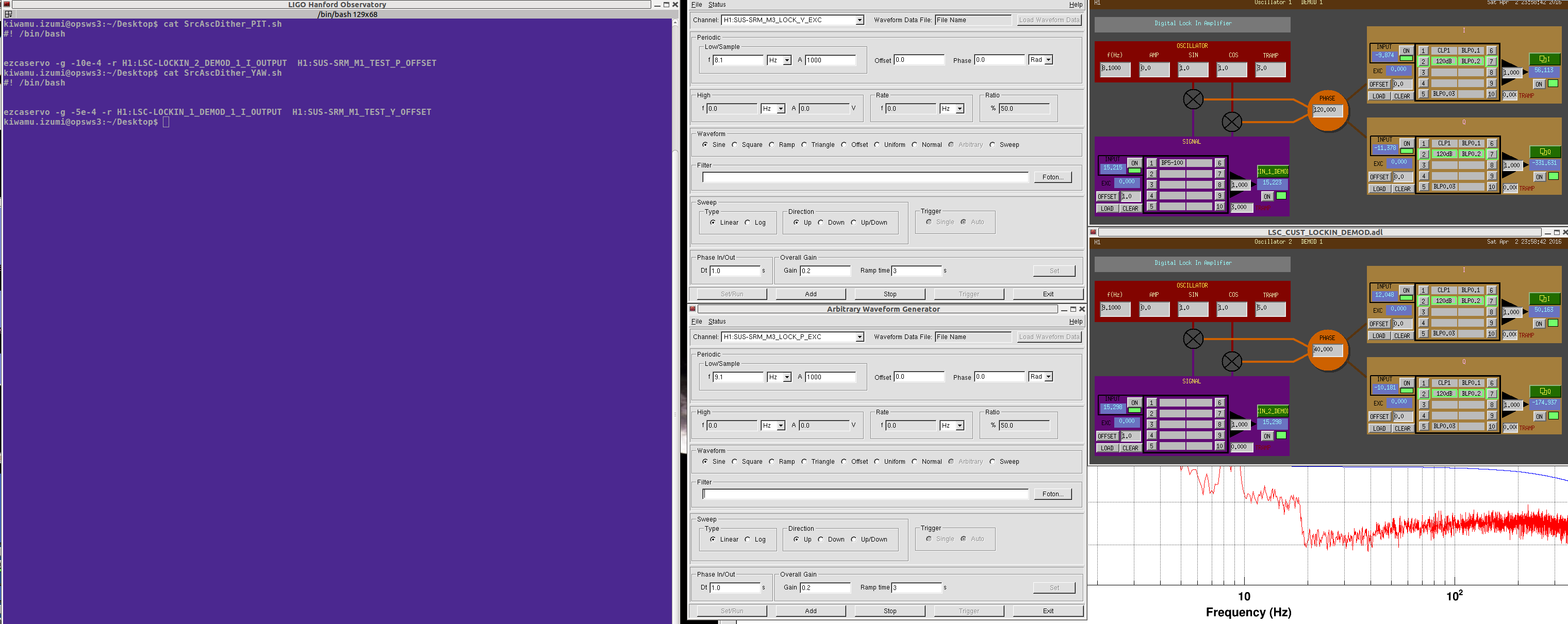
By the way, in order to keep the cavity pole at its highest during the swept sine measurements, I servoed SRM to the manually adjusted operating point by running a hacky dither loop using awg, lockin demodulators and ezcaservos. I have used POP90 as a sensor signal for them. The two loops seemingly had ugf of about 0.1 Hz according to 1/e settling time. A screenshot of the dither loop setting is attached.
Probably interestinmg to take a look at ASC_ASA/B_36/90/DC, and see, if there is a better combintion available.
It occurs to me that we might try putting some offsets into the centering loops for the SRC WFS. Can we find a pointing location where the AS36 signals give us an optimal alignment for the SRC?
On a somewhat parallel thought, Evan and I wonder if we could set offsets in the SRC1 loops after choosing an alignment based on some dither lines? Maybe we don't want always-on dither lines, but we could use them to help us figure out what our optimal alignment is.
Here are some more data.
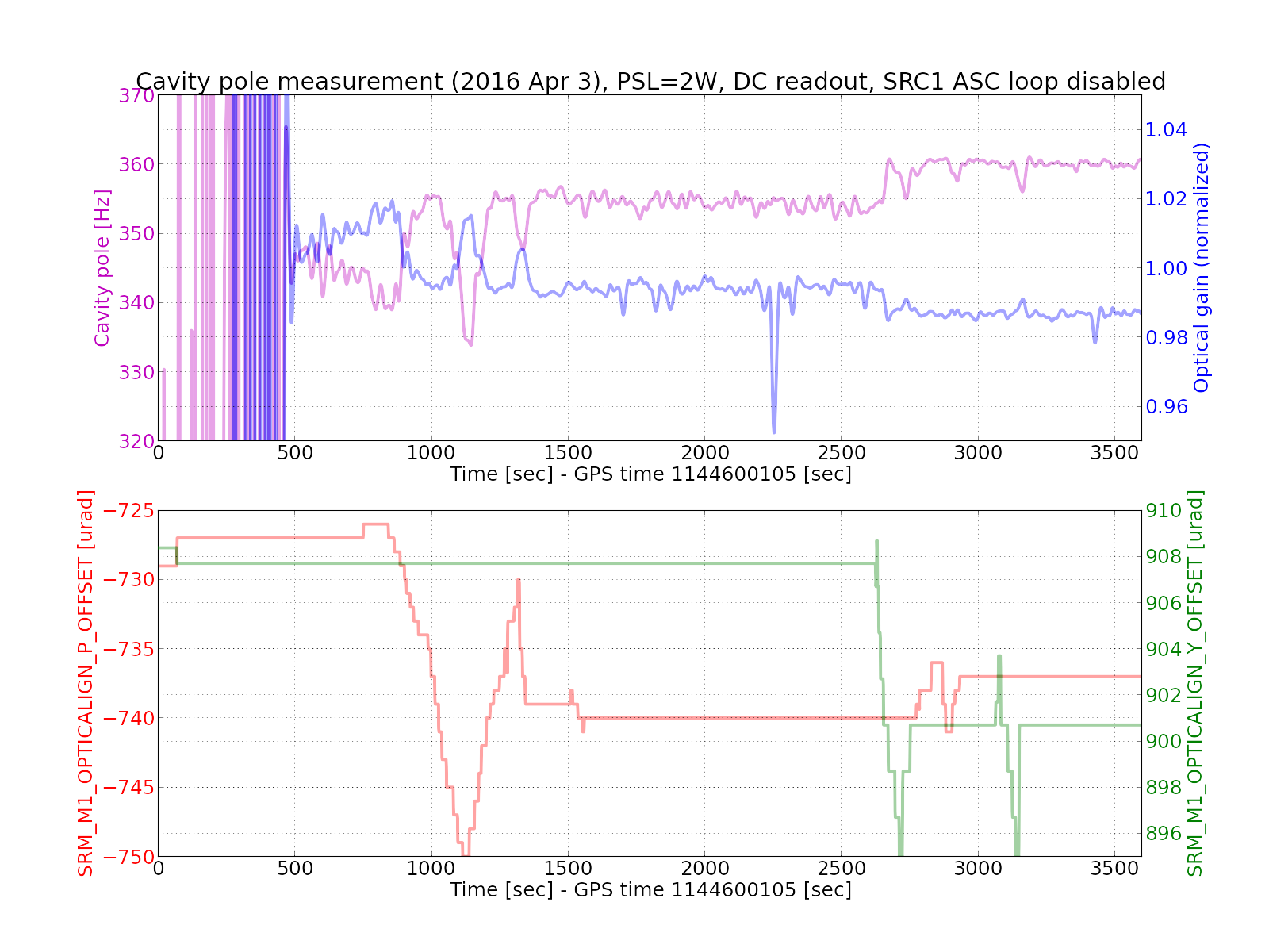
In this plot, full lock was achieved at some point between 0 and 500 sec. A small change in the SRM alignment offsets are due to the DRMI guardian completing the ASC offload to the top mass before decreasing the CARM offset. The measurement of the cavity pole and optical gain is valid only after 500 sec or so.
As I mentioned in the last ISC call, the cavity pole frequency and optical gain are anti-correlated -- one goes up and the other goes down.
The below shows a summary of my manual SRM alignment.
| Before | After | Difference (after - before) | |
| SRM PIT | -727 urad | -737 urad | -10 urad |
| SRM YAW | 908 urad | 901 urad | -7 urad |
As I wrote in the original entry, I steered SRM PIT and YAW by -10 and -7 urad respectively.
Also I attach a screen shot of trends showing the 2f RF signals during the same period.
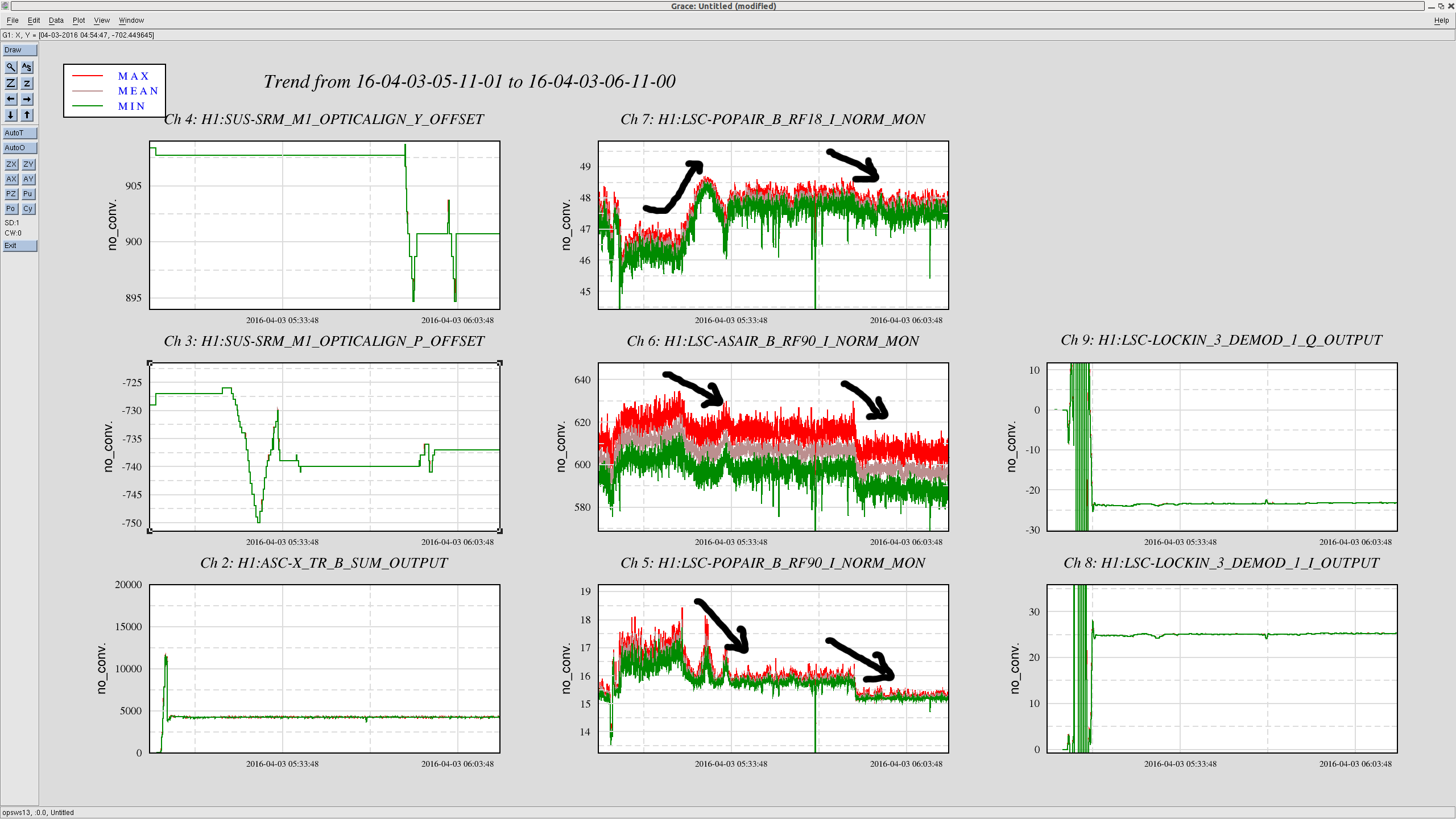
As the cavity pole increases the POP90 consistently decreases. This is what we expected because SRC sucks more light into it. POP18 also increased at the beginning which is good. However it decreased slightly after I aligned SRM yaw for some reason. The most outrageous one is AS90. As the cavity pole increased, the AS90 kept decreasing. I have no idea why.
Conclusion (again): it is the SRC alignment that changes the cavity pole.
[SRM and SR2 alignments]
I completely forgot about the SRC2 loop which controls the pointing of the output beam on to ASC_AS_C. This loop was active during my measurement silently correcting SR2 and SRM as I manually moved SRM. So I checked the witness sensors to see how much they actually moved instead of looking at my adjustment of the SRM alignment.
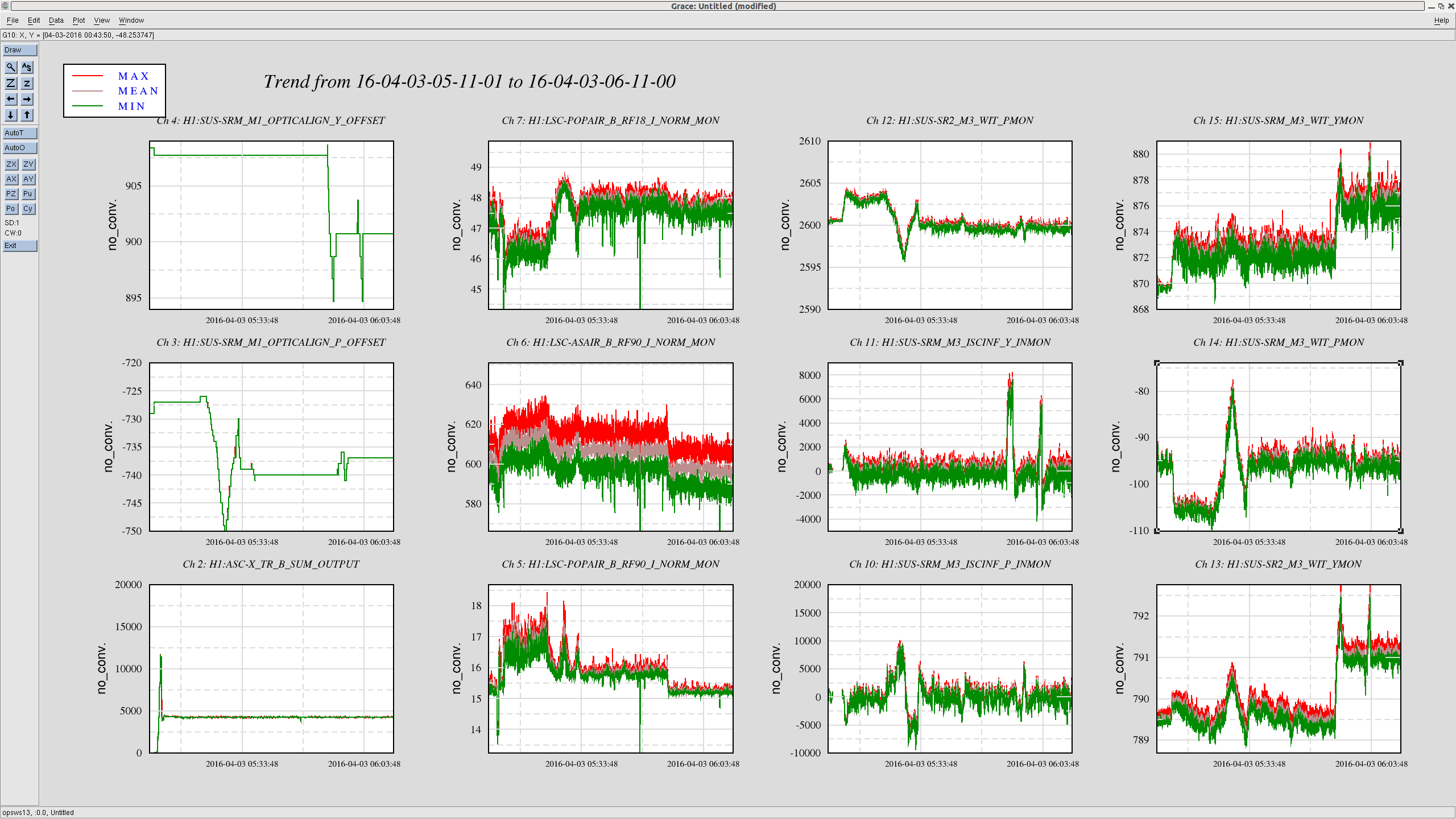
As you can see, SRM actually moved to the opposite direction in its angles due to the SRC2 loop counteracting on my adjustment. In total they have moved by the amounts listed in the table below.
| before | after | difference (after-before) | |
| SRM pit | -105 urad | -95 urad | 10 urad |
| SRM yaw | 873 urad | 876 urad | 3 urad |
| SR2 pit | 2603 urad | 2600 urad | -3 urad |
| SR2 yaw | 790 urad | 791 urad | 1 urad |
[A finesse simulation also suggests that the cavity pole is a strong function of SRs' alignment]
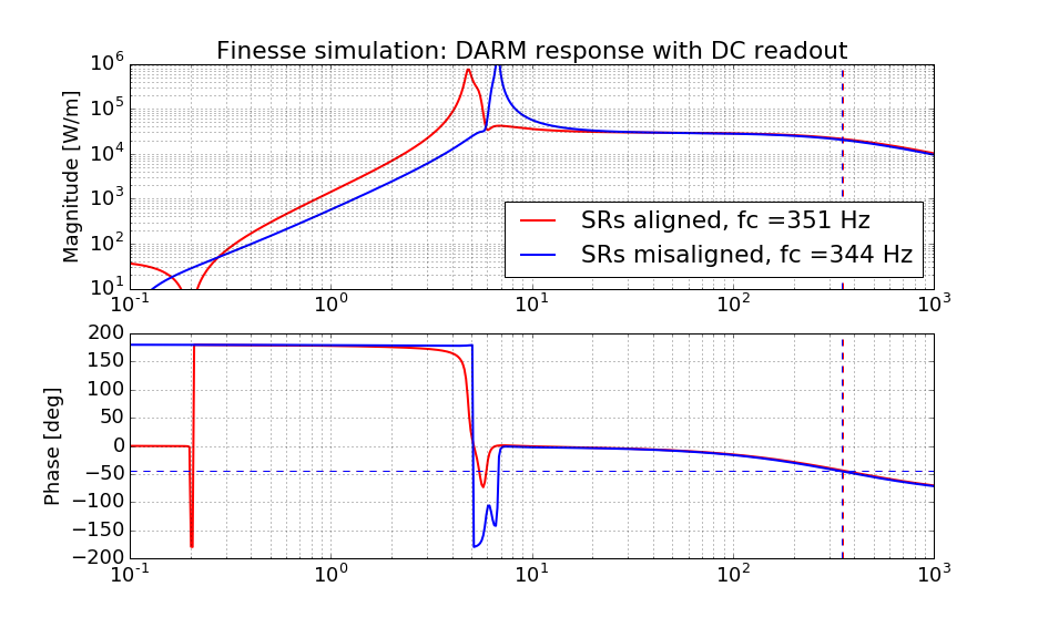
With the above misalignment values in hand, I then ran a finesse simulation to see if I can reproduce a similar result. Indeed, I could change the cavity pole from an optimum of 366 Hz to 344 Hz in the simulation (while my measurement was from 360-ish Hz to 345-ish Hz). The attached is a simulated DARM response with and without these misalignment.
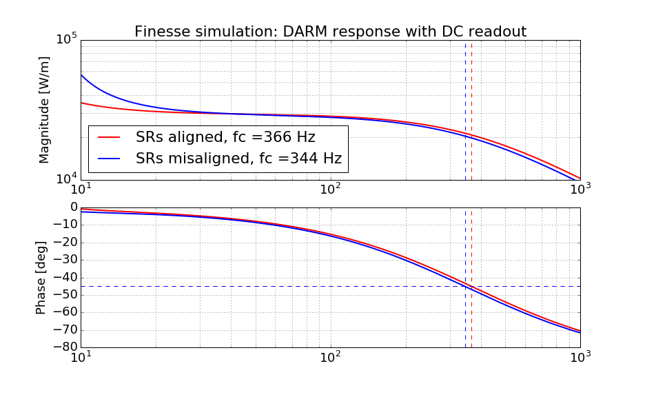
Because I was too lazy to fit out the effect of the time delay and next FSR peak, I simply searched for a frequency point where the phase rotates by 45 deg as a cavity pole frequency. This probably makes the absolute calibration of the cavity pole somewhat inaccurate, but the difference between the two cavity pole frequencies should be moreorless accurate.
Also I attach the finesse code in pdf format.

Addendum:
In the finesse simulation, the DARM response showed some difference at low frequencies between the two results. So I re-ran the same code and extended the frequency range to 0.1 Hz. It is seemingly due to a radiation pressure effect. I don't have a good explanation why it changed by SRs' alignment.