WP 5823
I have edited the h1lsc and common lsc models in order for us to be able to route the TR signals to the intensity stabilization system. As a result, the LSC model is now able to output a linear combination of TRX_NSUM and TRY_NSUM through a DAC. This signal can be then routed via an analog cable to the ISS, enabling us for a 3rd ISS loop.
To really engage this loop, one still needs to pull a few meter cable from the DAC output on the ISC field rack to the ISS module (either TRANSFER_1 or _2 analog input) in the same rack area. Additionally, to shave off undesired DAC noise above 10 Hz, we need an SR560 or equivalent in this analog path.
[Modification on the common lsc model]
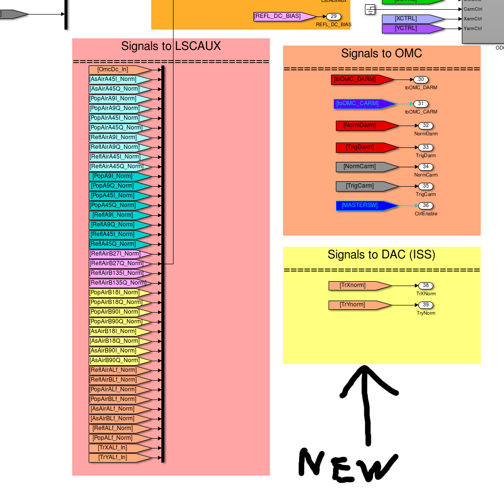
I have added two new outputs. Because the TRX and TRY were already acquired in LSC and properly normalized, only things I added are two "From" tags and two outputs. The modified version is uploaded to SVN. For LLO, they can just terminate these two outputs at the top level until they need these signals.
- Attachment 1 shows the two new outputs in the common lsc model.
[Modification on the h1lsc model]
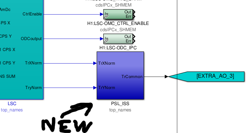
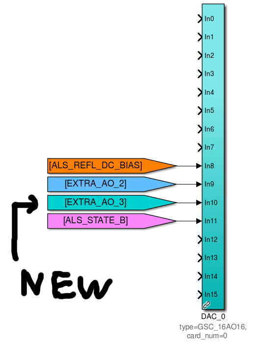
I have added a new subblock called "PSL_ISS" in which I placed a matrix to combine the TRX and TRY signals and placed a filter. The output of this subblock is then routed to channel 11 of DAC0. Because DAC0 was occupied by an unused channel ALS_STATE_A, I have disconnected and terminated ALS_STATE_A. This should not impact on anything. The model is checked into SVN. After the installation of the new model, I checked the output signal with a voltmeter at the floor and it was doing what it should do.
- Attachment 2 shows the new subblock.
- Attachment 3 shows the DAC output
[Medm screen]
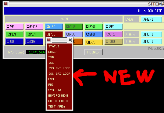
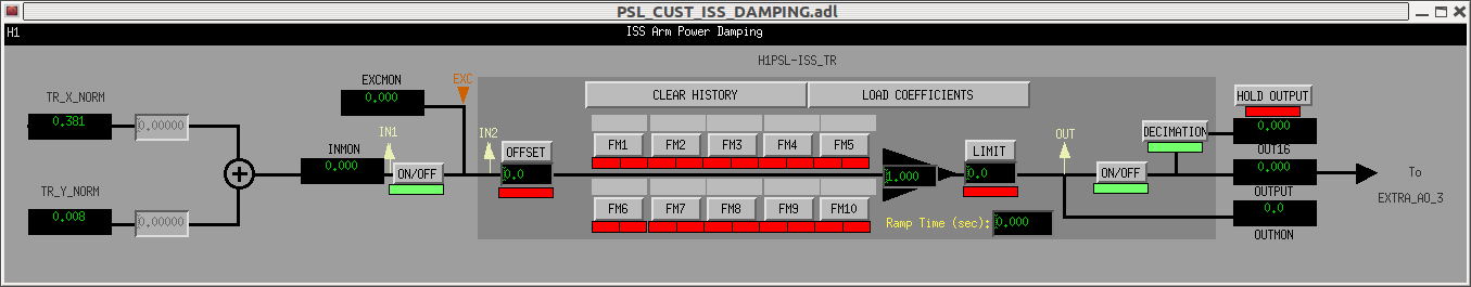
I made a medm screen for this new ISS loop. It is accessible from the PSL tab on SITEMAP. This screen is also checked into SVN.
- Attachment 4 shows the PSL pulldown tab on SITEMAP
- Attachment 5 shows the new screen.