A BSC-ISI model update about a month ago changed the St1-2 feedforward and sensor correction infrastructure. Before, there were independent feedforward and sensor correction paths, each receiving both L4C and T240 signals, meaning each sensor was getting sent twice. Now, there is a single path that gets shared to both the St1-2 feed forward and sensor correction banks, which means if we want to do both sensor correction and feedforward, we need a blend filter. For now, I've cannibalized the Quite_90 filters to do this, but it's likely this will need some more thought.
What I've done for now is taken the Quite_90 high pass (the L4C component) and used the relationship (low_pass) + (high_pass) =1 to design a complementary low pass filter. I started by taking the Quite_90 high pass and multiplying it by the L4C response to get it in a complementary form. In addition, the blend filters do the integration of the seismometer signals, which I don't need, so I had to multiply the high pass by a zero at 0 to convert it from (nm)/(nm/s) to (nm/s)/(nm/s). The complementary low pass is then just 1 - (high pass).
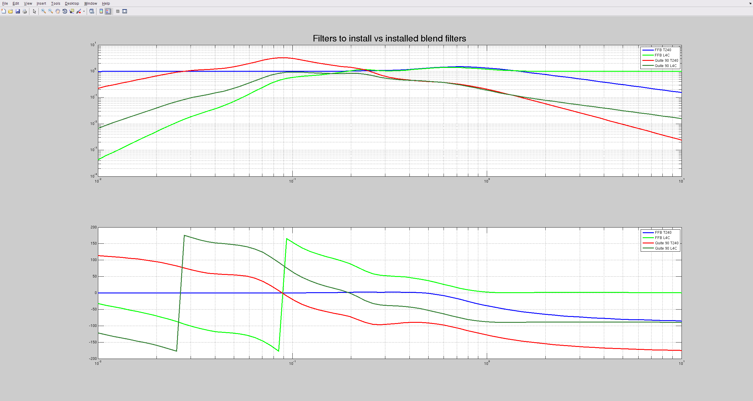
My first plot compares the resulting filters with the originals, where green (FFB L4C) and blue (FFB T240) are the Feedfoward blend filters and brown (Quite 90 L4C) and red (Quite 90 T240) are the St1 blend filters.
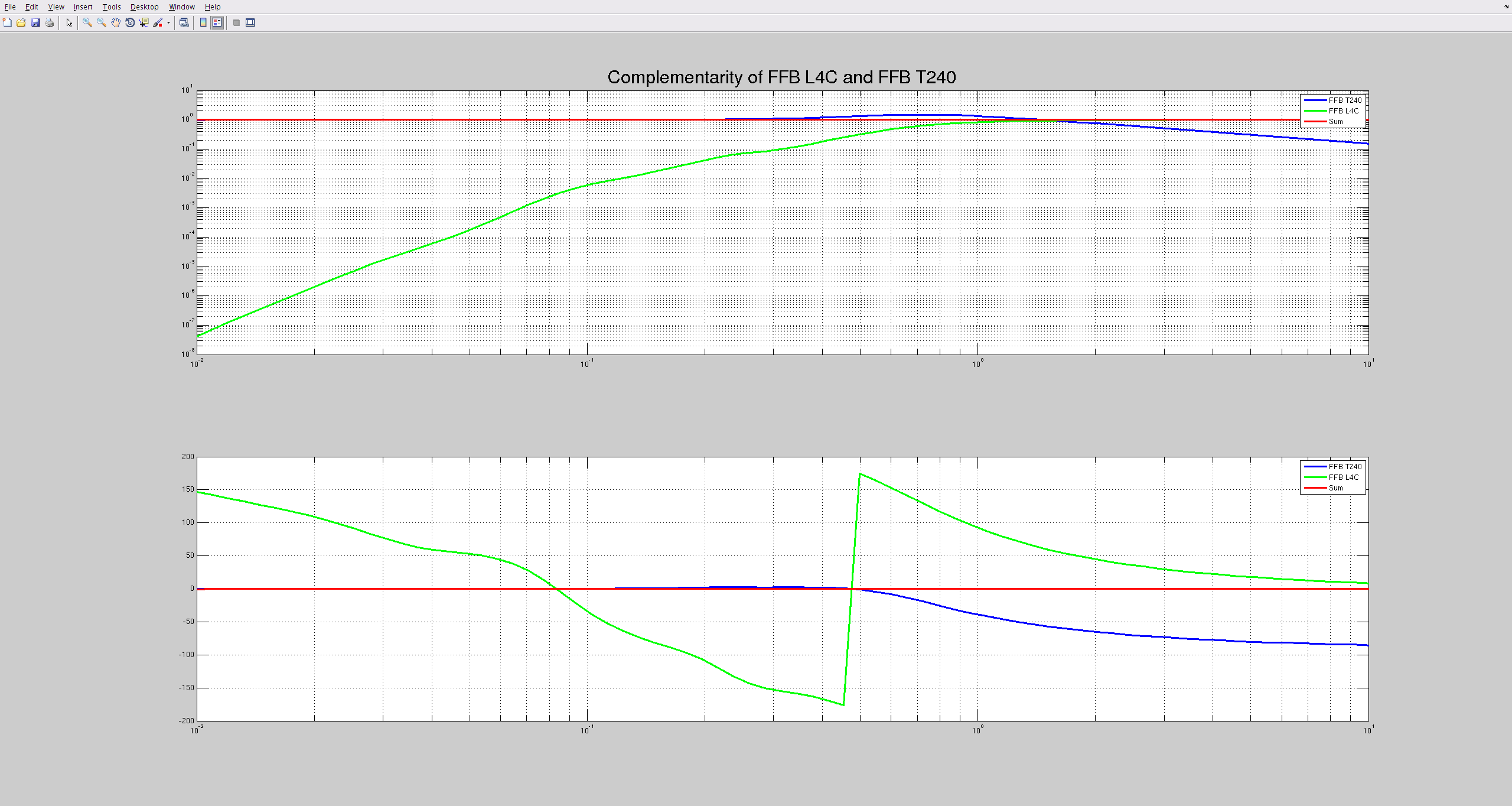
The second plot shows the complementarity of the FFB filters, showing that (low_pass) + (high_pass) =1. The final high pass then needed the L4C inversion added back in, to account for the L4C's frequency response.
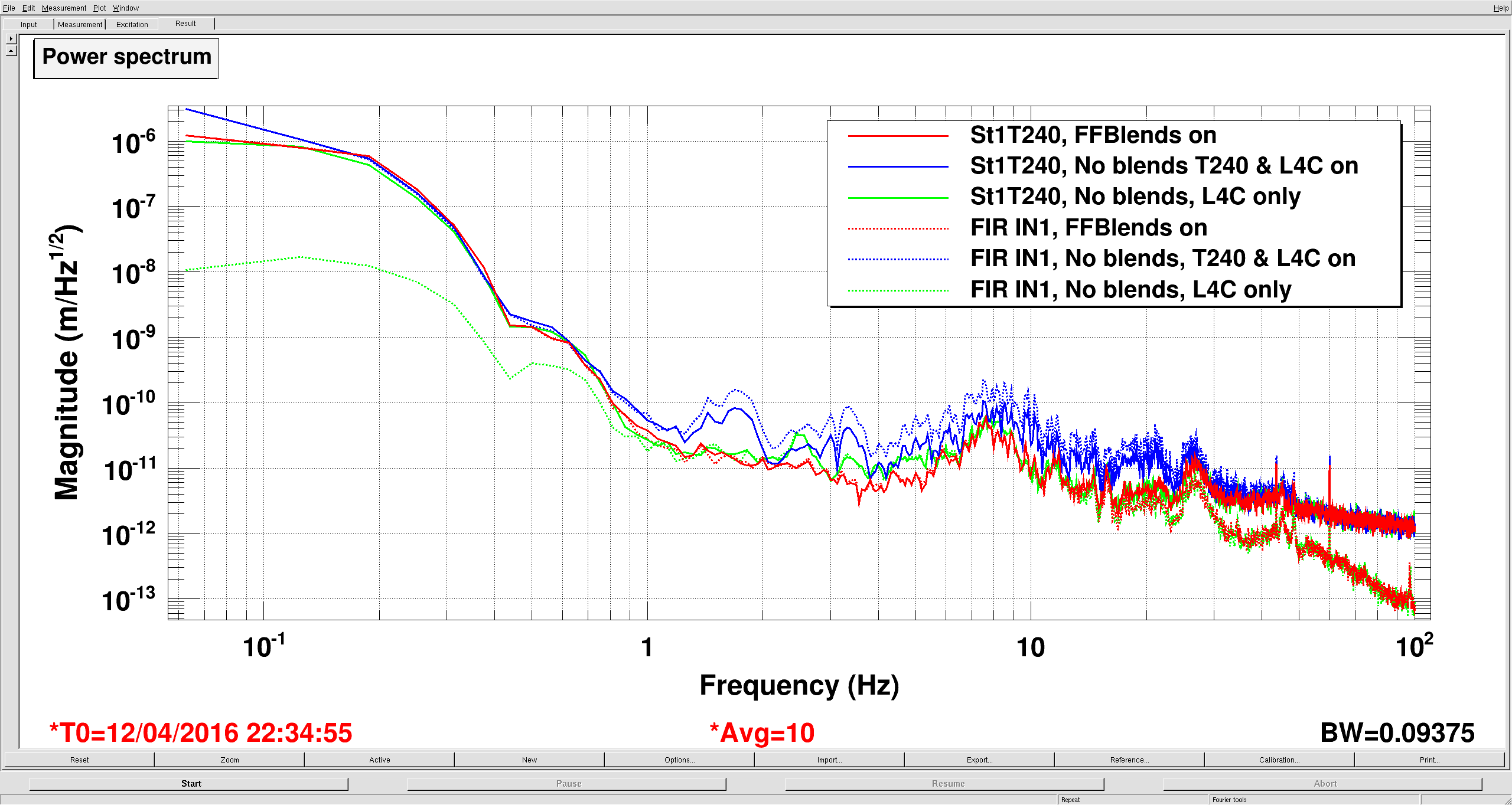
The third plot shows how accurately the blend filters sum the two signals. To check, I looked at the St1 T240 signal (solid lines), and compared that to ST2 FIR IN (dashed), which gets the output of the blend banks. For this measurement, I turned off all feedforward and sensor correction to ST2.
-The red traces are with the FFB blends turned on, so the dashed red line is the blended sum of the L4C and T240 signal. Seems pretty good.
-The blue line is with the FFB blends turned off, but the inputs and outputs turned on, so the dashed blue is just the sum of the L4C and T240 signals. Compare this to the solid blue, you can see this is clearly wrong above a hz. Below a hz the L4C acts like it's own high pass, so it doesn't contribute much here, as you'll see soon.
-The green traces are with the L4C alone. Remember, the solid line is the T240, but in this case, the dashed line is just the L4C. The response below 1 hz is low, because this motion is below the L4C's resonance, so the L4C is less sensitive to motion at these frequencies. This is why blends invert sensor responses.
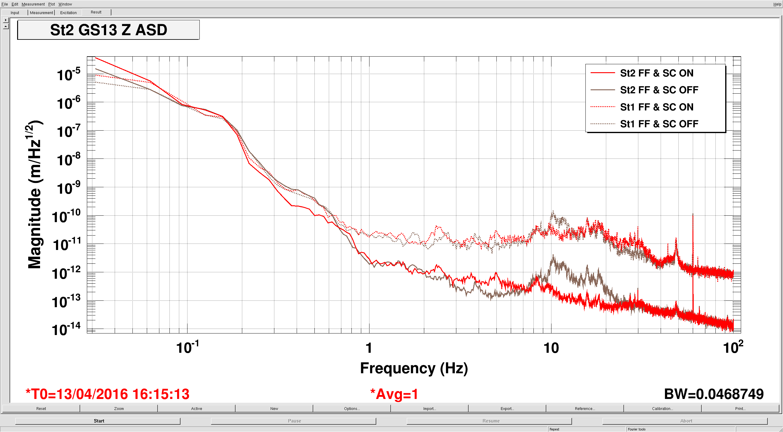
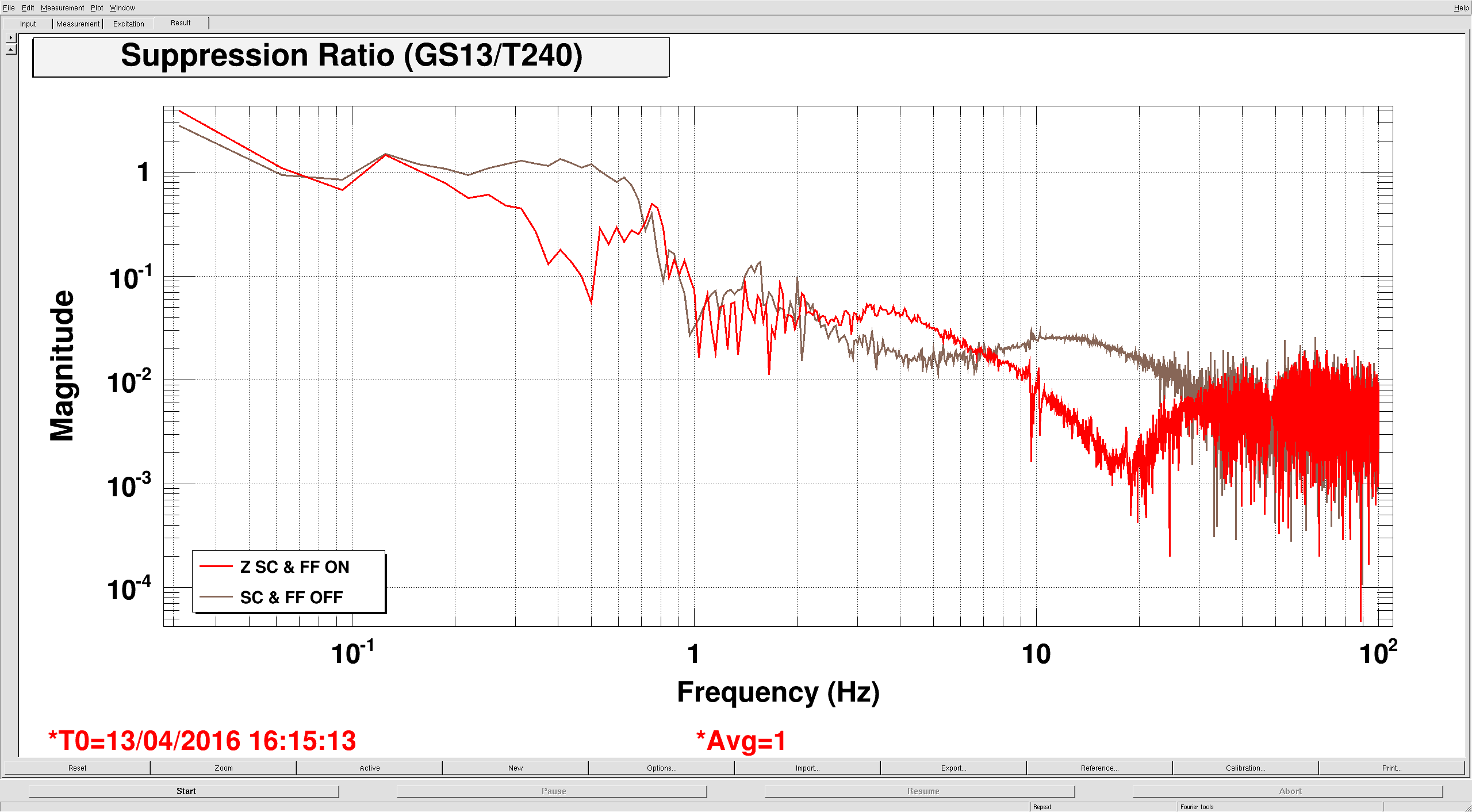
The fourth plot shows the St1 T240 & St2 GS13 performance on ETMX in Z, the only dof where I'm currently running both feedforward and sensor correction. The red traces are with St1-2 FF and SC on, the brown traces are off. Again, seems to work like it should. The fifth plot is the suppression (the ratio of St2 motion to ST1) for the on and off configurations.
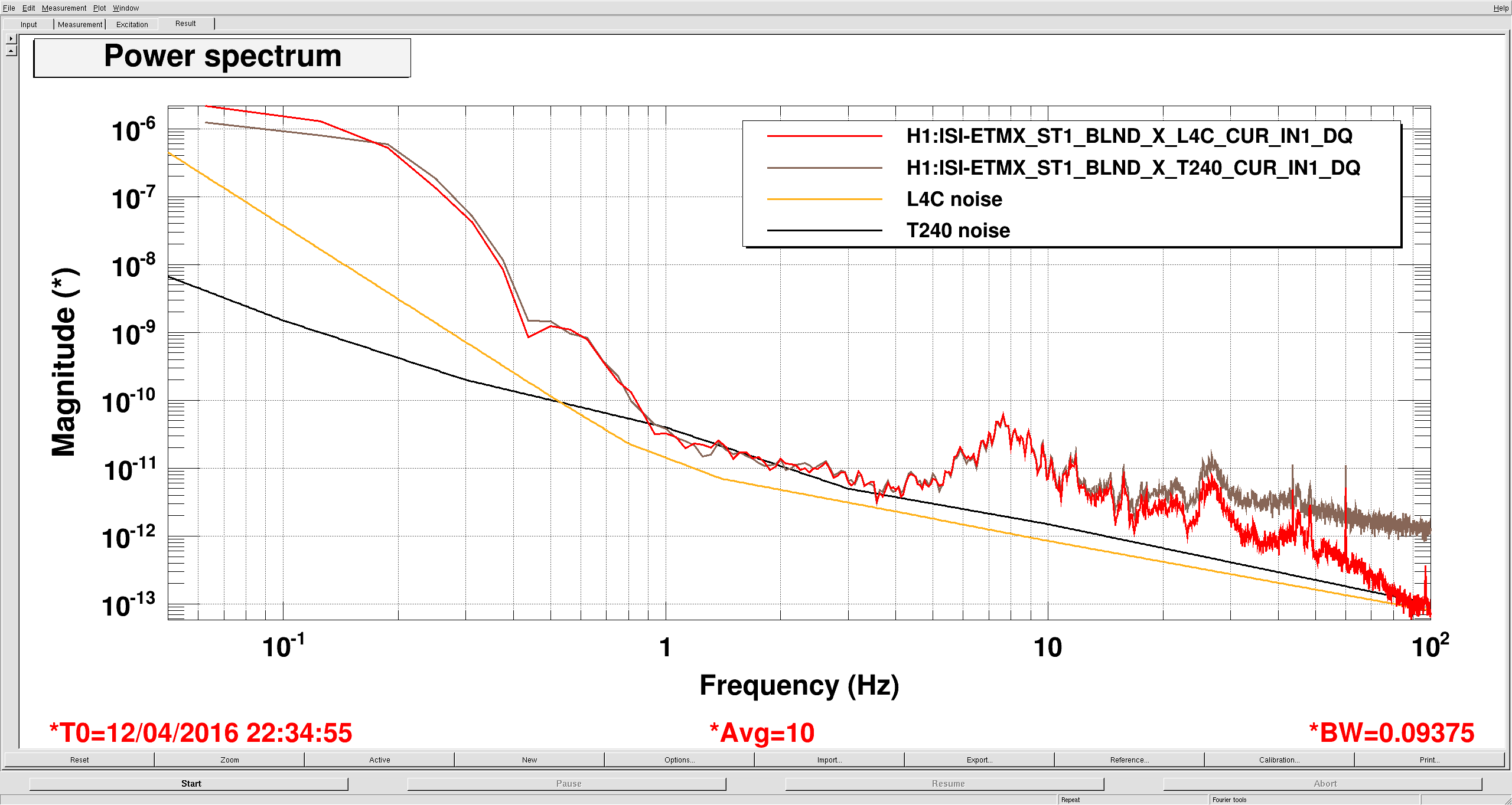
While I was taking these measurements, I realized that the St1 performance is limited by T240 sensing noise at around 1-3 hz, see my last plot. I don't know if we can do anything about it, but it's interesting.
These filters are now installed and running on all BSCs, on all dofs. This has been captured in the appropriate snaps, as well.