Summary:
Filter configuration for ISS 1st loop to generate RIN channels (H1:PSL-ISS_PDA_REL_OUTPUT and PDB) doesn't look good. It seems as though we're somehow chosen to use inferior of the two filters in place both for "CALI_AC" and "CALI_DC", assuming that D1001998-V2 (PD circuit diagram) and D1001985-V2 (ISS circuit diagram) are correct.
I made somewhat better filter for "CALI_AC". For "Cali_DC" probably it's good enough to use the one we're not using. I loaded the coefficients for the new file for H1PSLISS from H1PSLISS_GDS_TP MEDM screen.
This doesn't affect the loop because these channels are not in the feedback loop, but making these filters right makes it easier for different RIN channels to be compared.
Details:
Reading D1001998-V2, D1001985-V2, T0900630, analog part of the monitor output for PSL-ISS_PDA and PSL-ISS_PDB ADC have analog z, p and k of [0.0723;2700;0.0707] Hz, [3.3607;130;3.12;2300] Hz, and 0.2, they're all in the PD box (ISS box is just the pass through as far as these outputs are concerned). These are DC coupled.
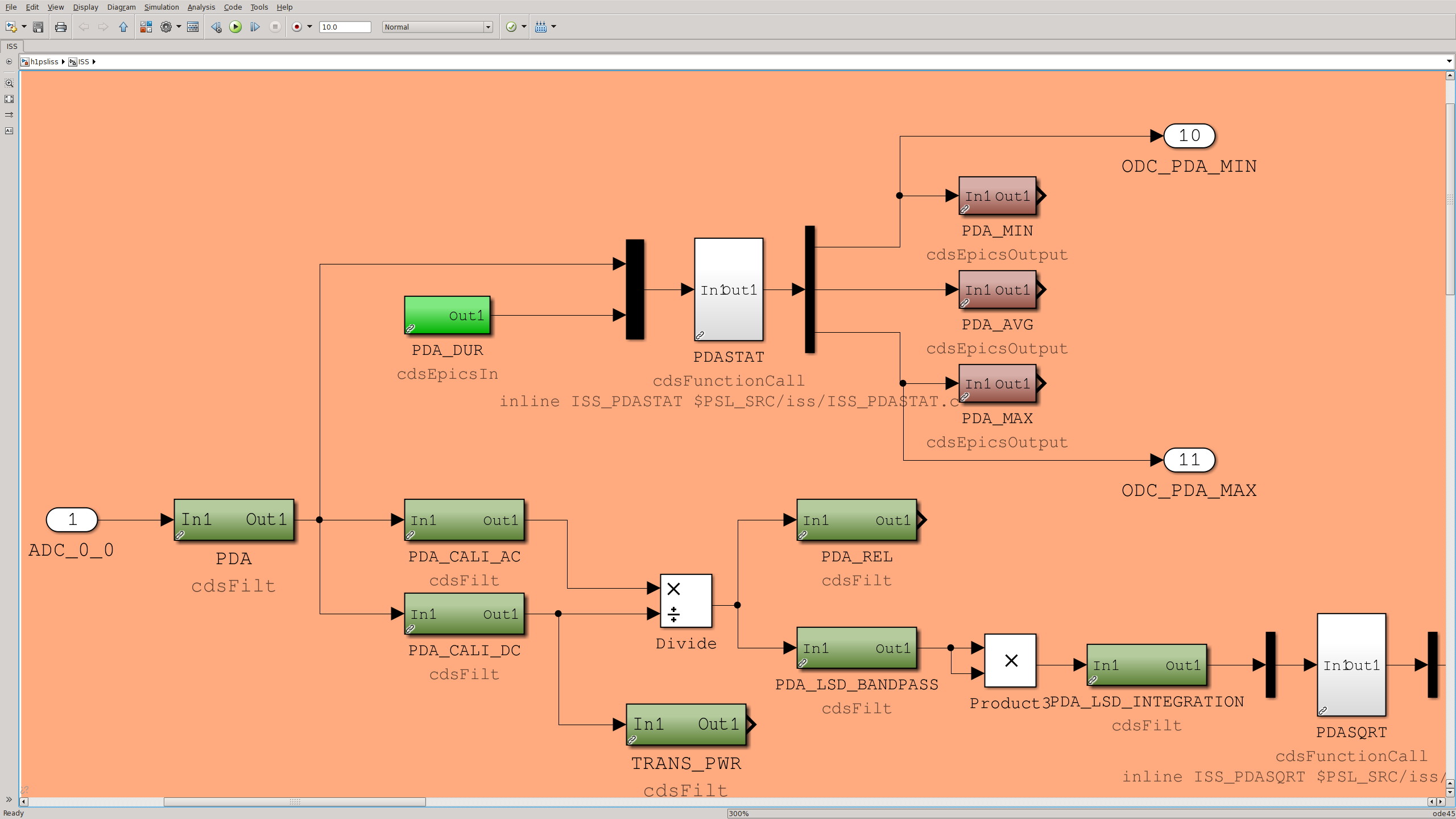
After they are received in the front end model, the signal is first converted to volts but not dewhitened by PSL-ISS_PDA, and then distributed to PSL-ISS_PDA_CALI_DC and PSL-ISS_PDA_CALI_AC. In DC the signal is low-passed, and in AC it's dewhitened and high-passed, and AC is devided by DC to give RIN (first attachment).
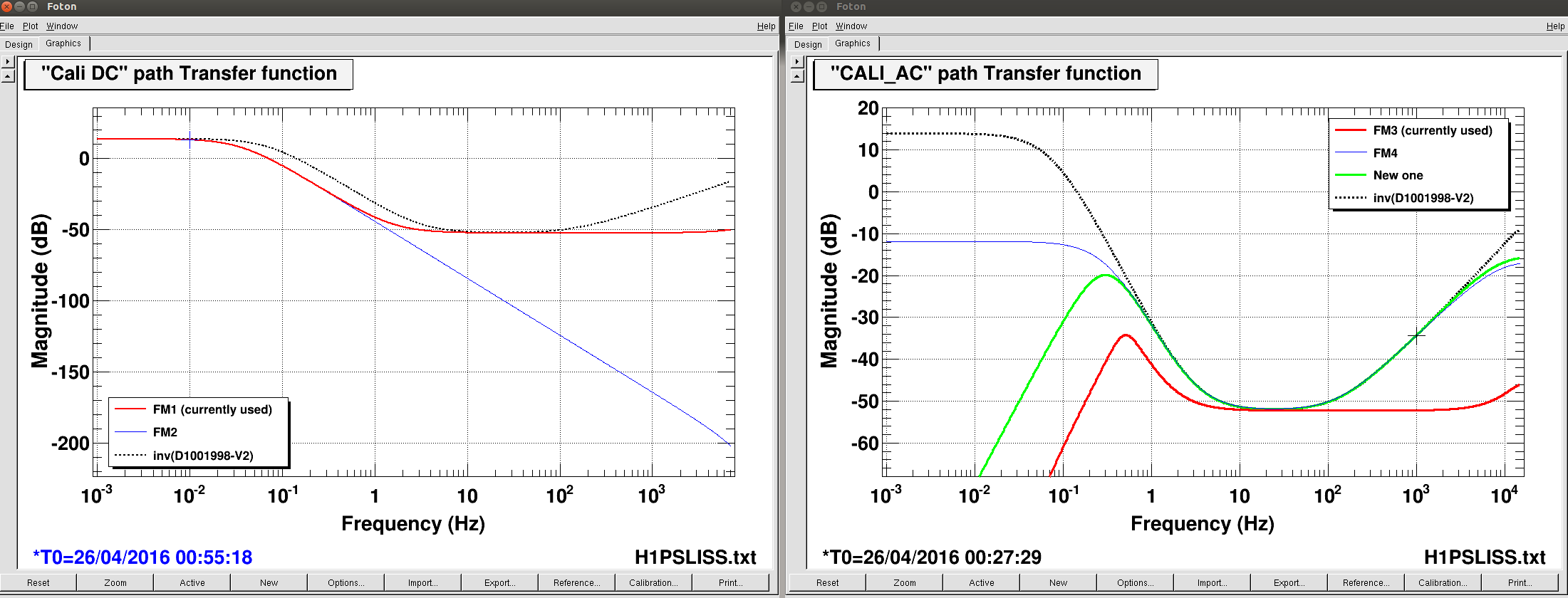
In CALI_DC path, there are two filters FM1 and FM2, only FM1 is used (second attachment left). I also plotted the inverse of the analog whitening transfer function including the DC gain in the same attachment. FM1 looks like a strange dewhite, nothing wrong with that, but I don't see any reason to prefer FM1 over FM2. Just use FM2.
In CALI_AC path, there are also two filters FM3 and FM4 (second attachment right). Compared with the inverse of the analog, it seems like the one in use (FM3) underestimates the RIN by 18dB at 1kHz. FM4 looks better but it's DC coupled. I made a new filter (green) and put it in FM5.
It's kind of odd that we're keeping DC gain factor in two different parts (CALI_DC and CAL_AC) instead of upstream. However, moving this gain into upstream affects PDASTAT thing (see the first attachment again), so I'll not fix this.
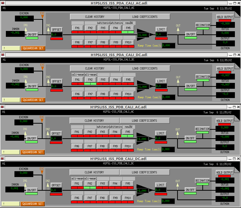
I have enabled the filters that Keita created/recommended. The attached screen shot shows the new settings for CALI_AC and CALI_DC for both PDs. Additionally, I changed the sign of CALI-ACs in order to make them consistent with CALI-DCs which had a minus sign in the gain field.
The SDF table is updated accordingly.