peter.king@LIGO.ORG - posted 16:08, Tuesday 26 April 2016 (26794)
ISS work/status
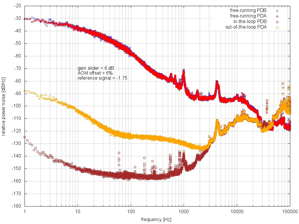
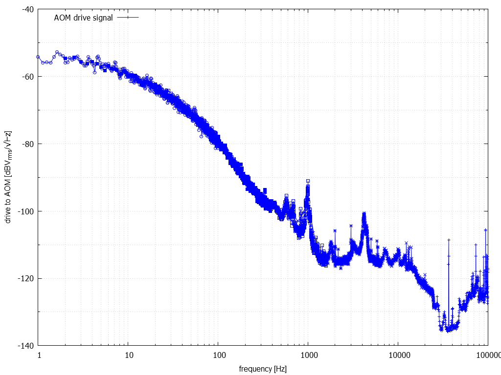
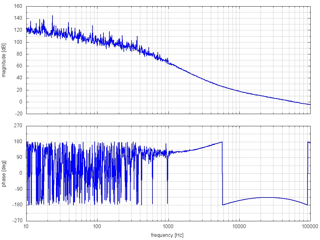
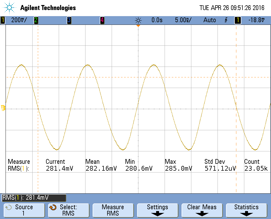
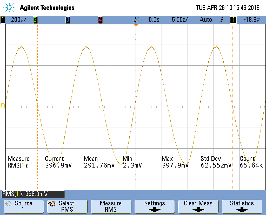
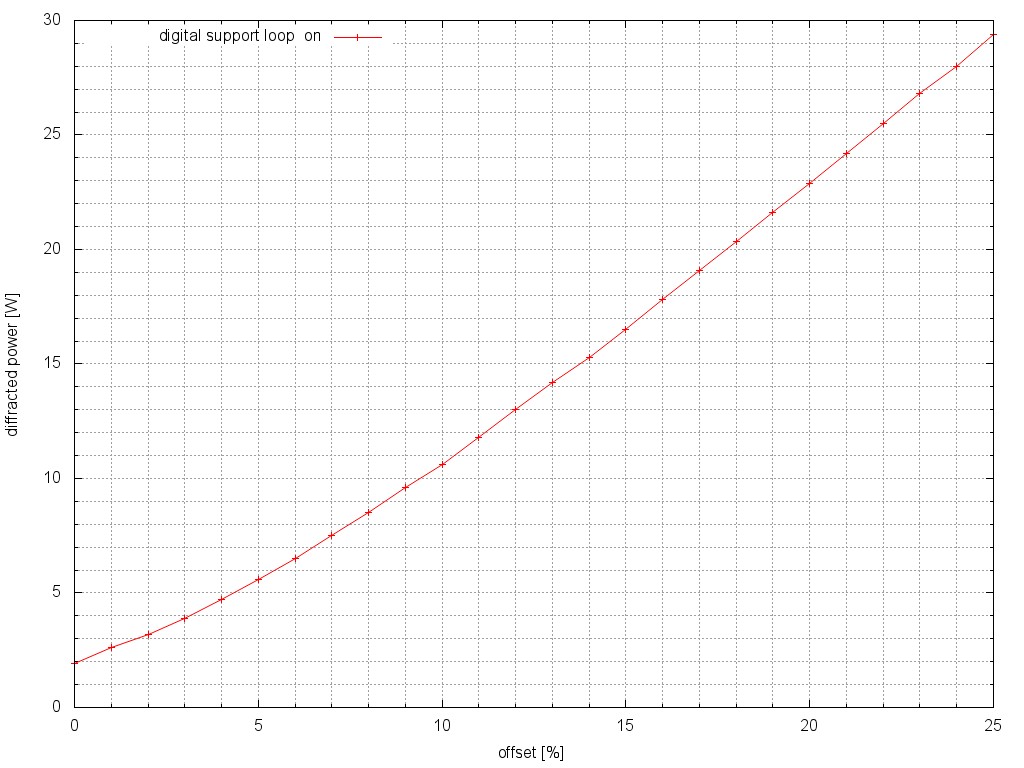
Attached are some data traces from today's work on the power stabilisation.

After tweaking the alignment of the ISS AOM, I found that the maximum diffracted
power in the first order was 4.1 W when the offset slider was at 10%.  aomfreqinput.png
shows the 80 MHz into the AOM as things were - a 9 dB attenuator was in the path.
0.28 Vrms corresponds to about 1.6 mW.  The AOM driver input should be around 6 dBm.
aom[5-7].png show the AOM driver input with 5-7 dB attenuators respectively.  A 5 dB
attenuator was left installed.  The 0.45 Vrms corresponds to ~6 dBm.  The resulting
diffracted light is shown in DiffPwr.jpg.  This hopefully will solve the saturation
issues observed earlier.

rpn2.jpg shows the output of PDA and PDB.  PDB being the one used as the sensor for
the loop.  The agreement between PDA and PDB is okay for the free-running spectra.
With the loop closed, the agreement is not so good below 3 kHz.  Increasing the
servo gain, increased the noise beyond ~10 kHz.

AOMControl.png is the spectrum of the drive voltage to the AOM when the servo
was locked to yield the above noise measurement.

ISSTF2.jpg is the transfer function measurement.  UGF is ~58 kHz with a phase
margin of ~25 degrees.

Obviously plenty of work to do in order track down the source of the excess noise.
Hopefully the power stabilisation will not be so fickle.
Images attached to this report