Superseeds alogs 26910 and 26924
Bad news: There is lots of MHzish pick-up on the cables to the ITM L2 coils: ~50mVpk
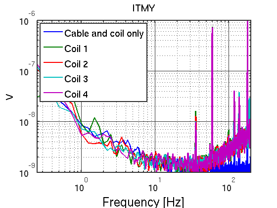
Good news: The ITM L2 coil noise at low freuency is very good: 1.5nV/rtHz at 25Hz, and we might not care about all that pickup.
Details:
The 10Hz harmonics reported in alog 26910 was a measurement problem, generaterd in Rai's preamplifier box (D060205). The cables pick up on the order of 50mVpk at around 1MHz, which was amplified by 100x, causing slew-rate down-conversion.
This was fixed (in the measurment setup) with a 270nF capacitor in prarallel to the 23.8Ohm cable and coil resistance, resulting in a 24.7kHz pole to cut off the cable pick-up.
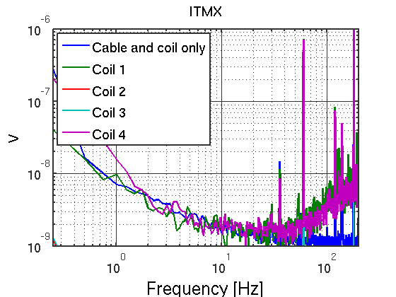
Plot 1 and 2:
ITMX and ITMY coil noise.
Configuration:
- Everything (coil driver, cable, coil) was connected. The breakout box was inserted between coil driver and cable to the satellite amplifier.
- The L2 cois drivers were both is state 3: Acq Off, LP On, which is the run mode. They are never switched for the ITMs.
- The coil driver inputs were left connected to the DAC/AI. I also sent a 100ctpk, 3kHz signal into H1:SUS-ITM[XY]_L2_DRIVEALIGN_L2L_EXC, corresponing to a 2.6ctpk signal on the DAC. I did this to make sure the DAC is as least flipping bits, which raises its noise level.
- A 270nF capacitor was put in parallel to the coil using a pomona box to avoid saturating the D060205-preamp.
- The preamp has a gain of 100. After the preamp a 100Hz low pass was used (1595Ohm and 1uF) to allow the SR785 to run in the lowest noise mode.
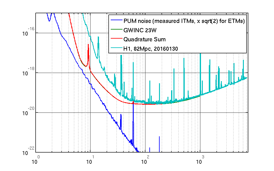
Plot 3:
Noise projection assuming incoherent noise and assuming the ETMs behave the same.
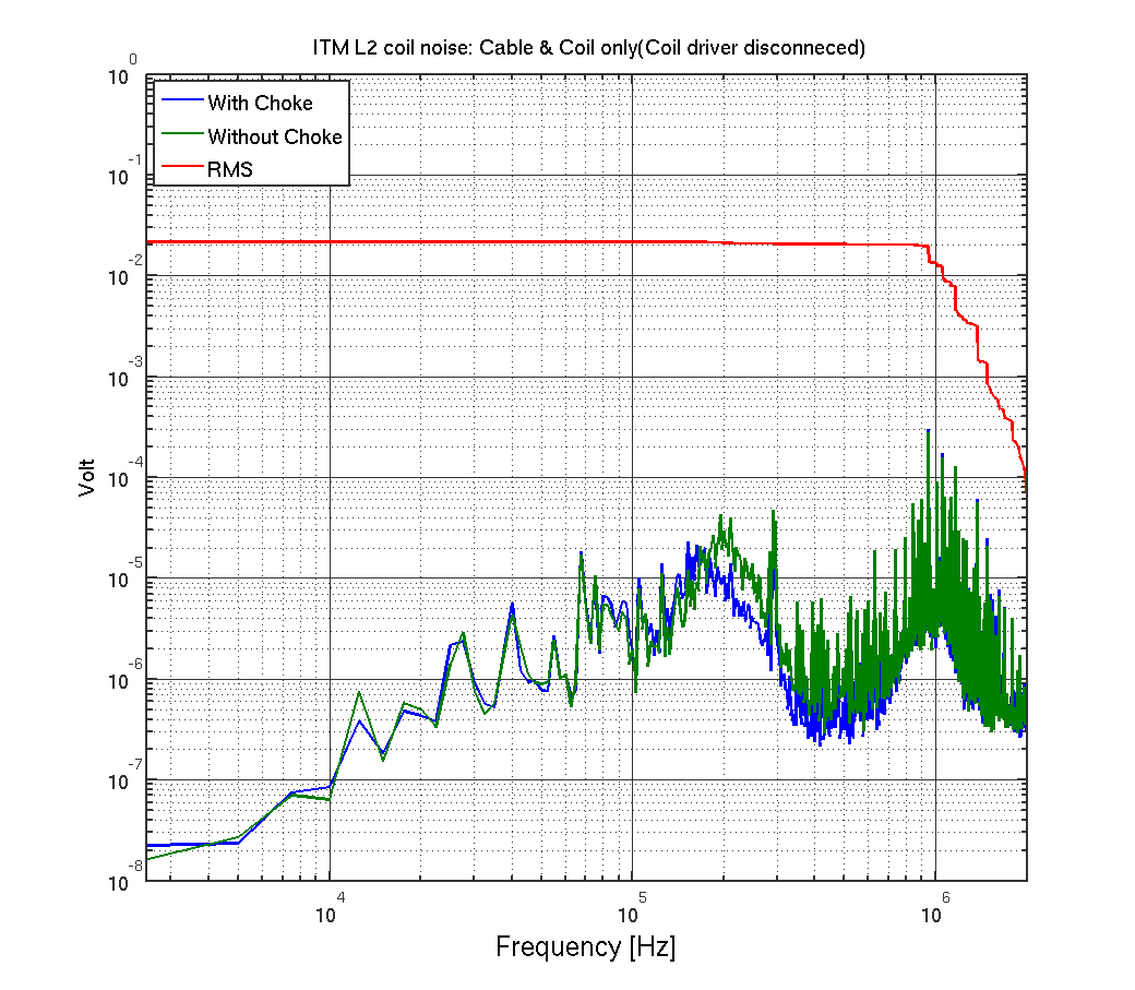
Plot 4:
High frequency noise pick-up on the coil cable (coil driver disconnected).
The dominant noise is at ~1MHz, broadband.
Shown are two traces: one in nominal configuratiuon (green), and one with an additional choke on the cable to the coils.
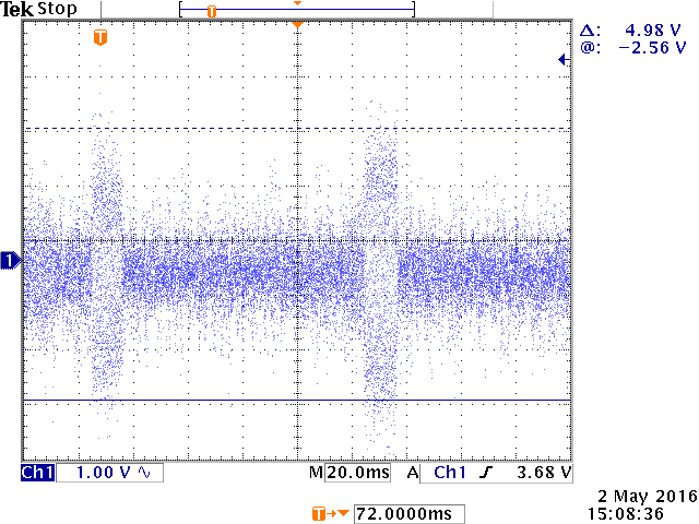
Plot 5:
Scope trace of the high-frequency signal (only the x100 amplifier is used). The signal is made up of ~10msec bursts every ~100msec.
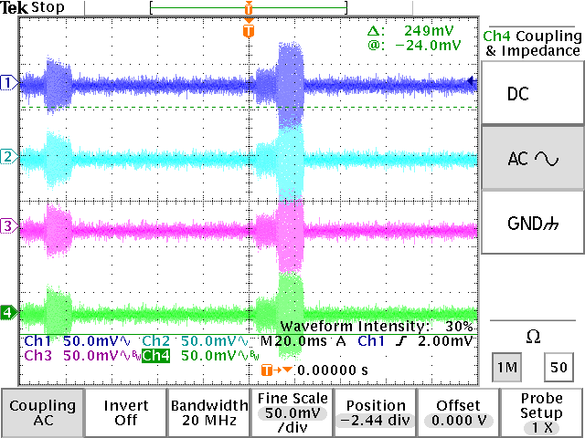
Plot 6:
All 4 coils (without amplifyer) directly connected to the scope. Note that the grounded inputs of the scope slightly change the signal.
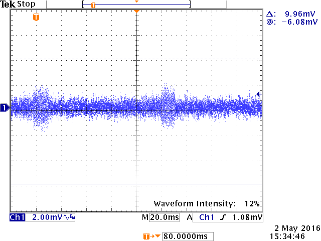
Plot 7:
Scope trace with only an antenna connected to the scope. The signal pickup was largest between the racks - I could not trace it to a source yet.
For reference, the data and matlab code is available at ~controls/sballmer/20160429/plotIt.m
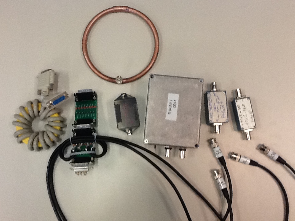
Also, since we probably have to do similar noise checks when we have the IFO back, here is the equipment I used: Top: Ring antenna Bottom, from left to right: choke, breakout card, 270nF parallel capacitor box, Rai's preamp box, 100Hz LP filter, AC coupling for looking at RF on the spectrum analyzer.
Plot 4. With the cable disconnected from the Coil drive the Shield is no longer terminated. This may contribute to the pickup.
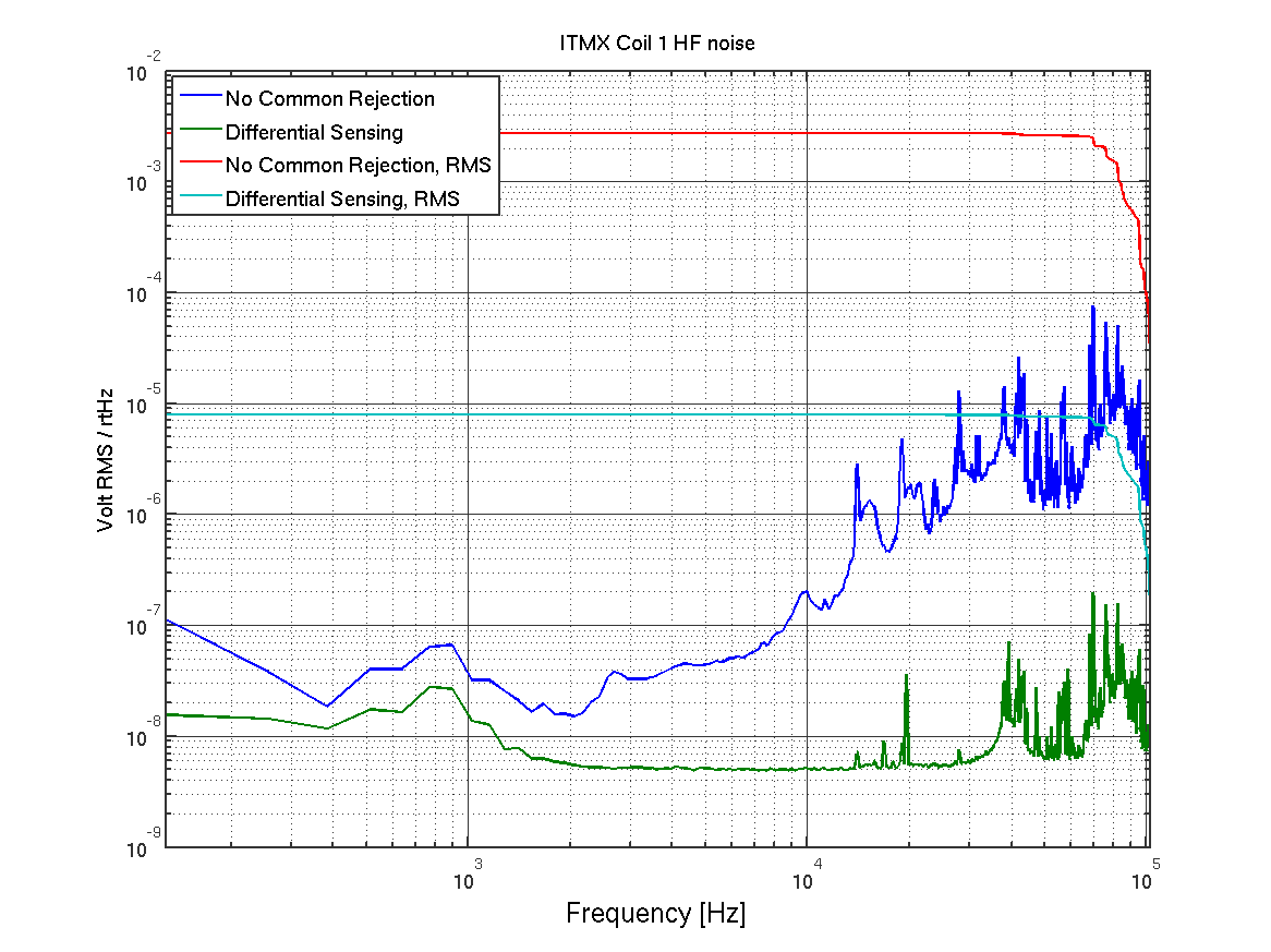
The high frequency noise coupling in in plot 4 is mostly common, and shows up because Rai's preamp has no differential sensing.
In the attached plot the noise seen on ITMX coil 1 is plotted, once sensed with Rai's single-ended preamp, once with an SR560 in differential mode.
Conclusion: This noise does not show up on the coil current.
However: The same common HF noise pickup seems to be present on all cables. This now makes me worry about the ESD: I suspect the ESD has much less common rejection, because the +400V and -400V comes in on different cables. Moreover, a broadband noise at 1MHz on the ESD will produce noise near DC due to the quadratic nature of the ESD coupling.
I also tried to use the antenna to locate the source. The field is strongest in a circle arouind the rack, suggesting the source might not be in the electorics room, but rather just brought in by all the cables.