Kiwamu, Tega, Nutsinee
Quick Conclusion: We are done for the day. The clipping is pretty much fixed but the heating profile remains ununiform. We will resume the work on Tuesday. CO2Y power has been set to zero while CO2X remains at its nominal power. The beam dump has been put back in front of the FLIR camera.
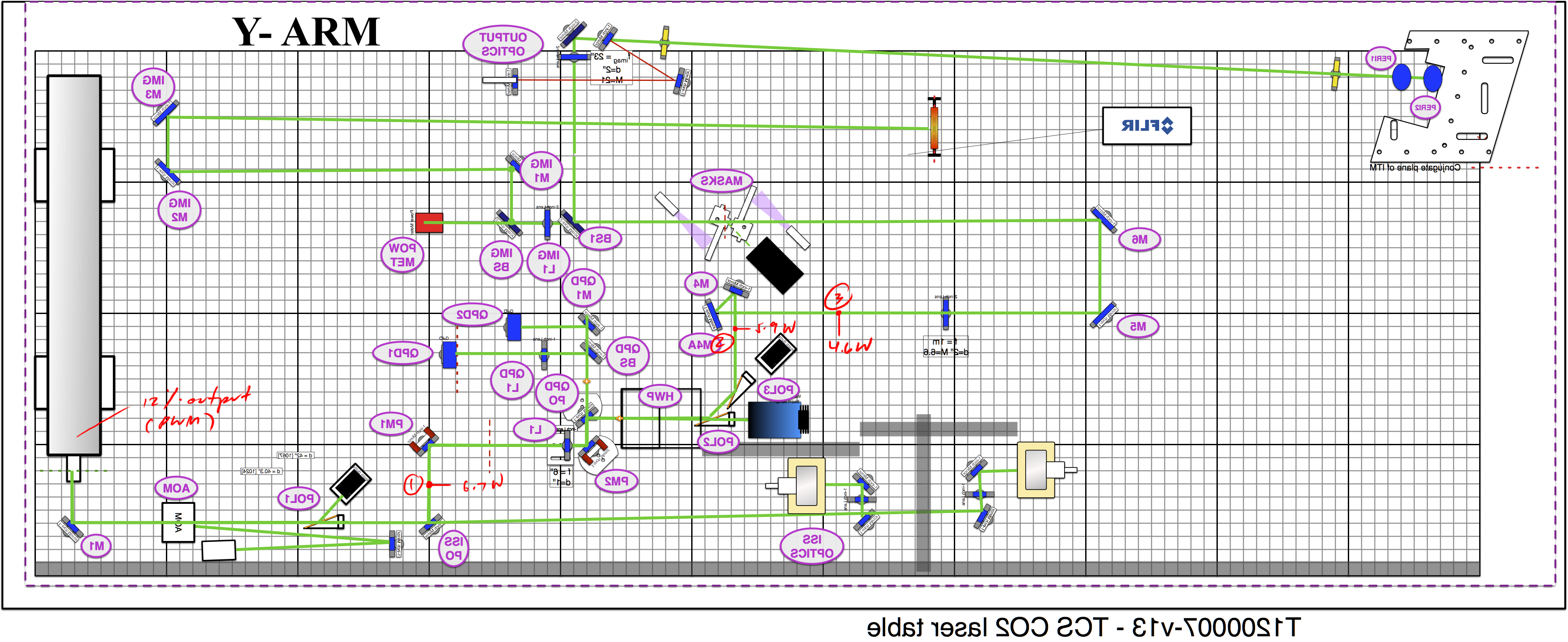
Details: Today we went back to the table and tried to find the clipping point somewhere around M4 and M4A mirrors because the low transmissivity we saw the day before (alog27369). Seeing that the beam profile looks good reflecting off M4 we measured the power again using a power meter with a bigger aperture. We measured more power this time and the transmissivity from point 2 to point 3 wasn't as bad (78% instead of 35% -- see first attachment). We moved on to fix the horizontal clipping on M5 starting by adjusting M4A mirror. After centered the beam on M5 we moved M5, M6, and moved the annulus mask position sensor away from the beam path by about a centimeter. We adjusted BS1 to align the beam through both irises and fine tuned the alignment using the steering mirror between BS1 and the first iris. We adjusted M3 slightly to center the beam spot onto the FLIR camera screen. Looking at the camera image we noticed the beam profile has temperature gradient by 2 deg C from the lowest to highest when the power was 0.15 W at the screen. We are not sure if this is critical but we can improve this on Tuesday. The beam dump has been put back in place before we closed out.
ALso by fixing this clipping we improved the maximum CO2Y power to the ITM from ~2.5 W to ~3.7 W.
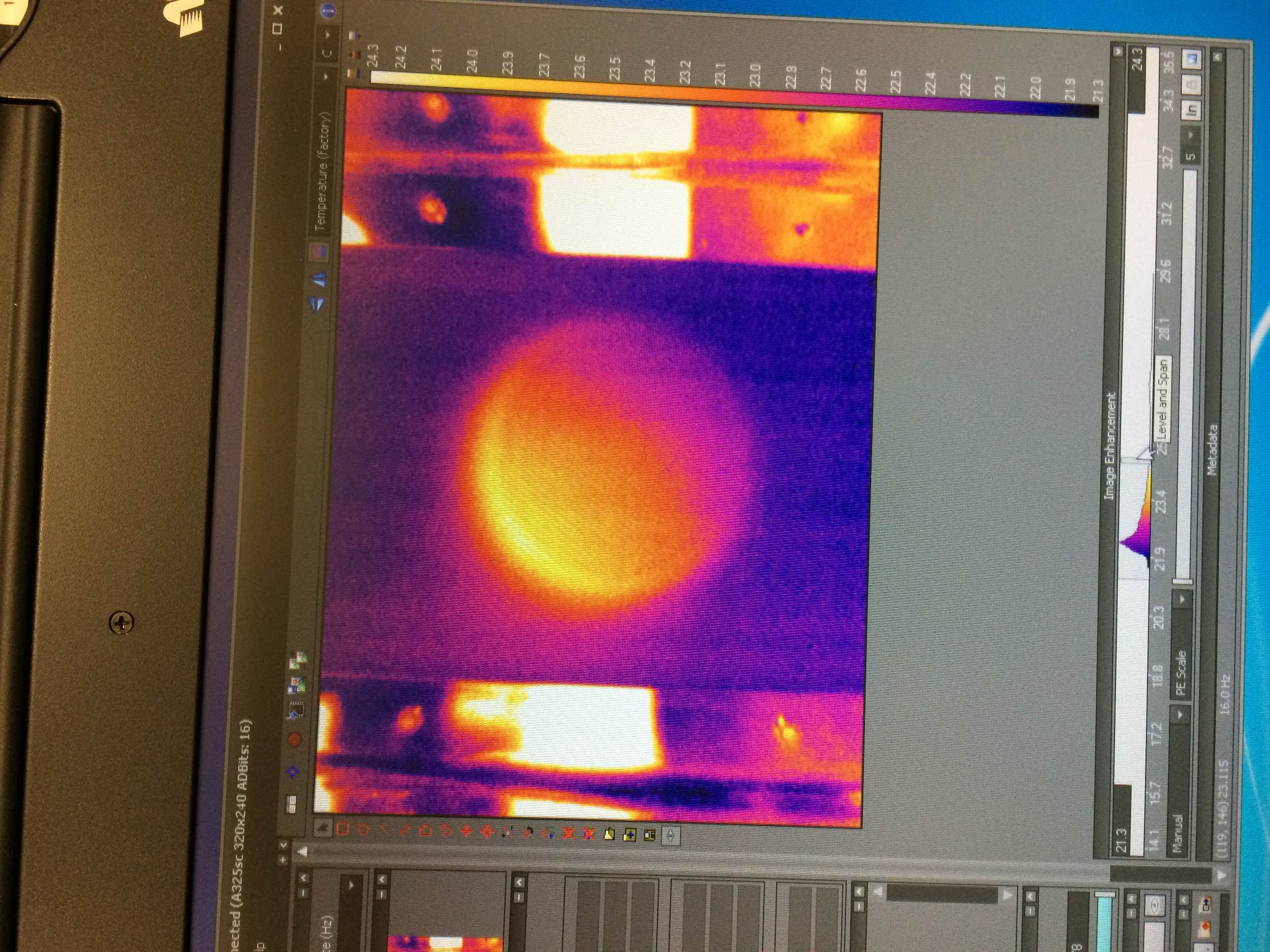
FLIR image yesterday
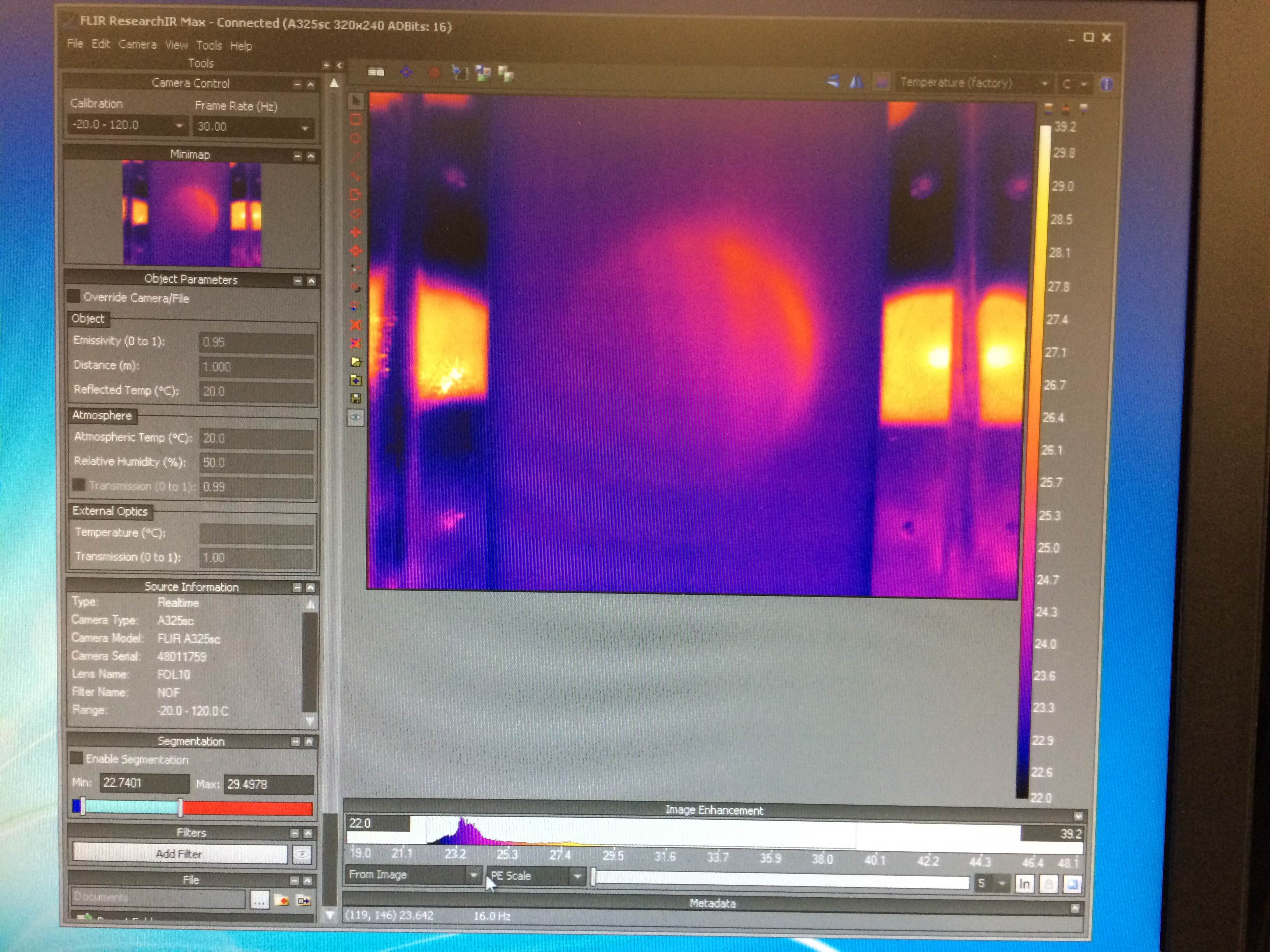
FLIR image today (I don't know why the image rotates. Use your imagination.)