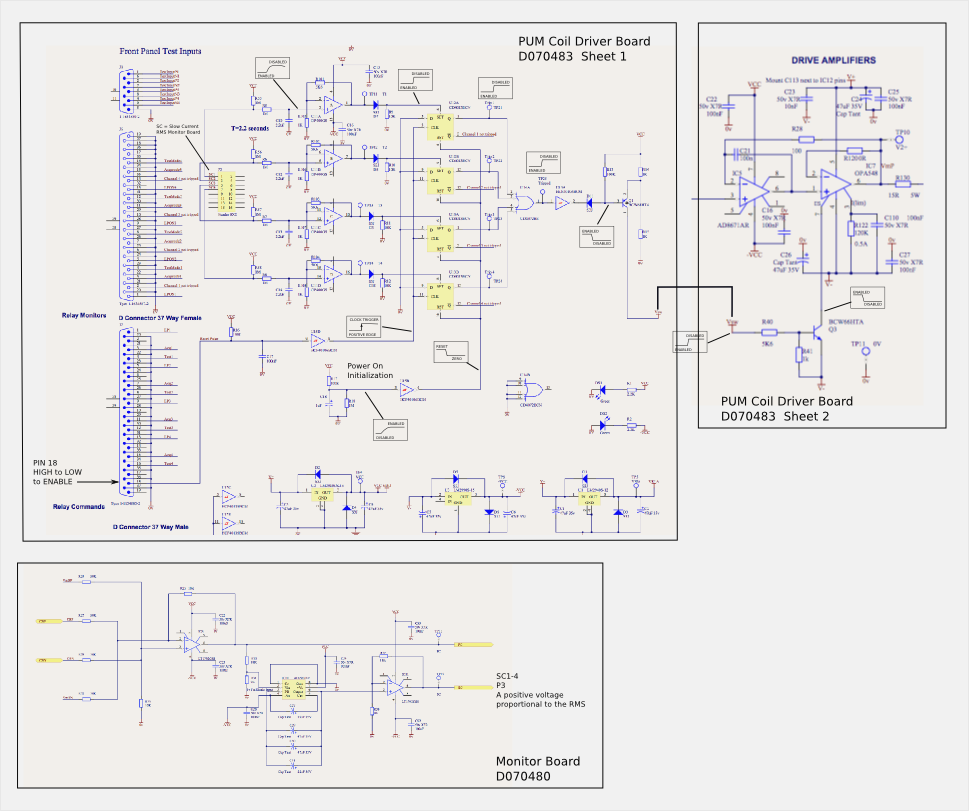
Attached are two illustrations: The first is a notional schematic of the pum rms "watch dog" showing the interconnections between the rms circuit, the "trigger logic", and the driver amplifier. The second drawing shows the signal levels through the circuitry. The information for these illustrations came from drawings D070483, PUM Coil Driver Sheets 1 & 2, and D0900975, Monitor Board. (The D0900975 is an annotated update of the old D070480 Monitor board.)
The resetting of the rms-wd is accomplished by either powering off, waiting a minute, and powering back on, which allows the reset circuit (R17, R18, C18, and U15B) to clear the D-flip-flops or a High-to-Low voltage transition on P18 of connector J7 on the PUM Coil Driver card. There is a binary I/O and software (MEDM button) available to do this remotely. Richard M. and Fil C. are checking the integrity of this. The state of the trigger D-flip-flops (tripped or not-tripped) is available on the MEDM screen for the PUM drivers.