We had three PI modes - 15522 of ITMX and 15541 of ETMX and 15542 or ETMY- ring up tonight and were only able to damp successfully ~40 W for a few hours; around 4am local time ITMX and ETMY began ringing up (despite fully driving both ESDs) and broke the lock.
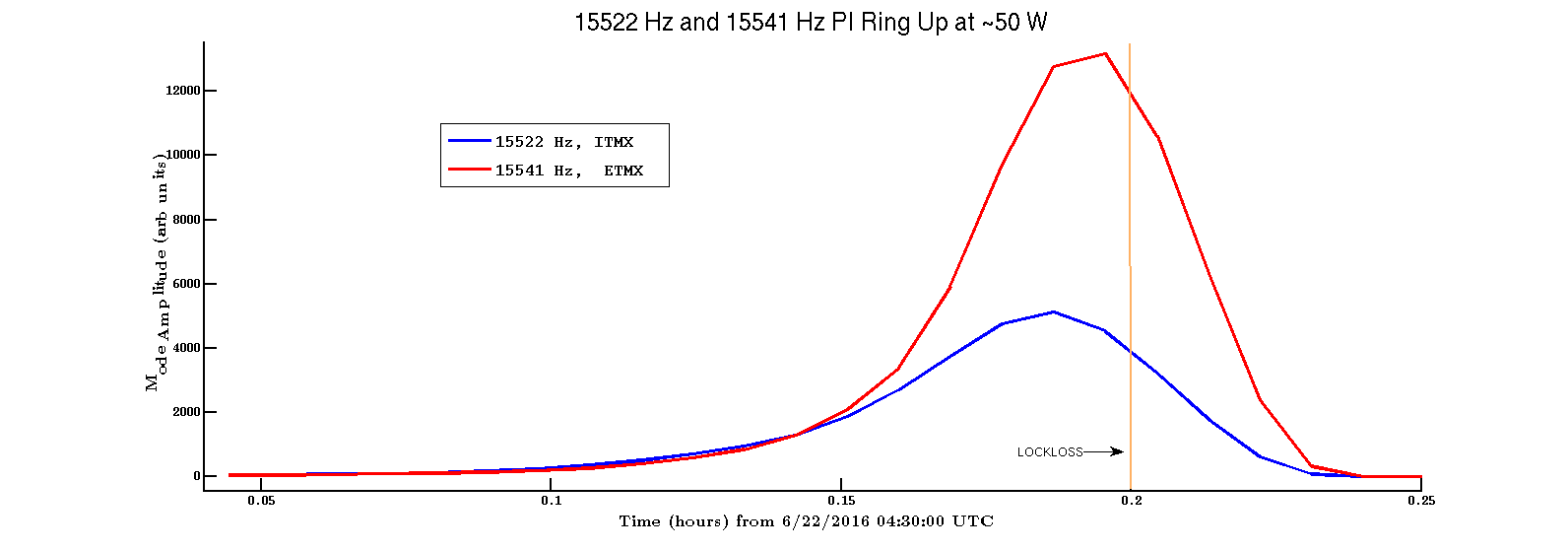
At 4:42 UTC we originally lost lock from ITMX and ETMX modes ringing up, shown below:.
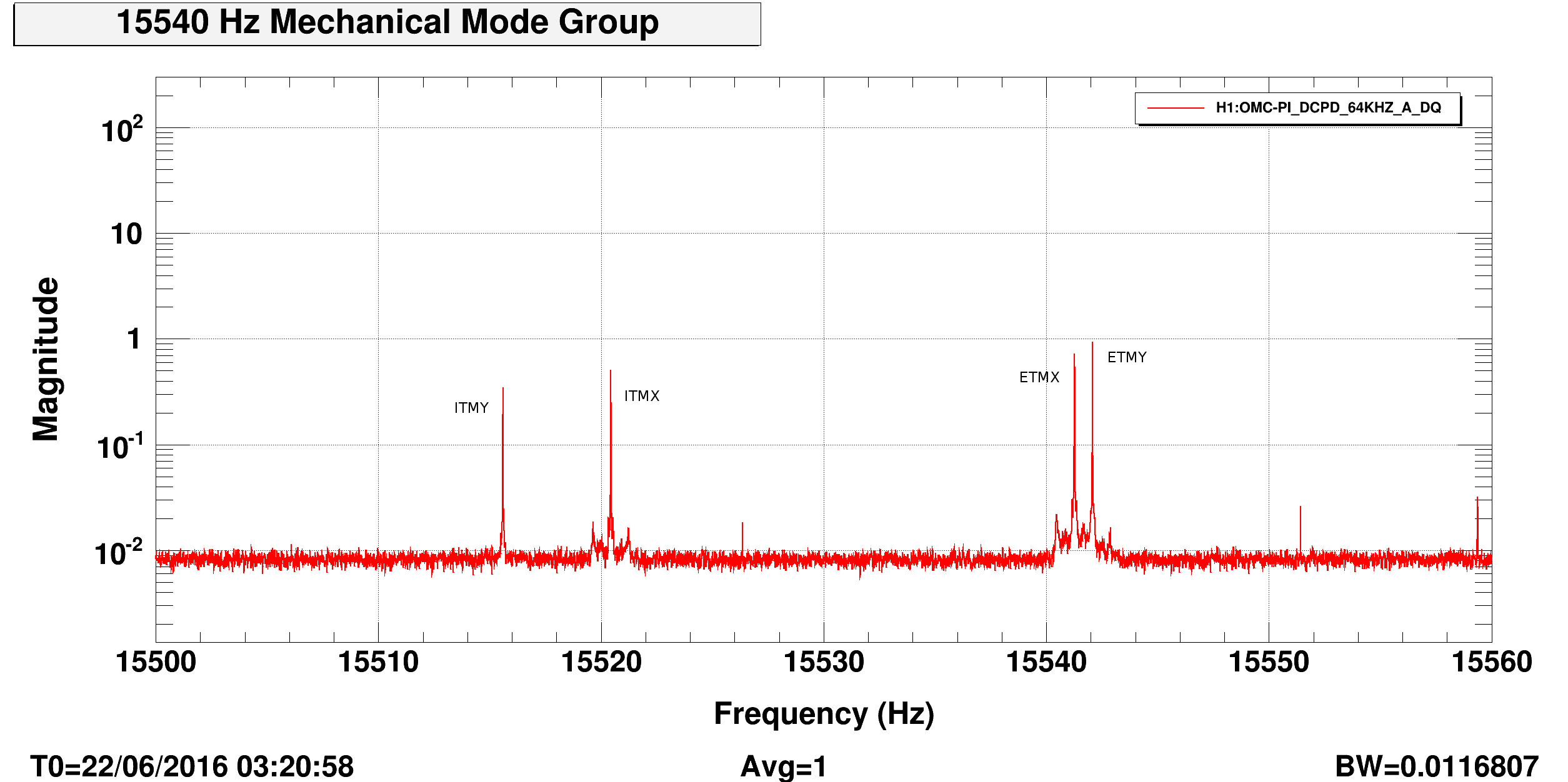
In low power, I drove and damped each test mass to match it with it's peak. Here is a spectrum in low power with peaks labeled for this 15540 Hz mode group.
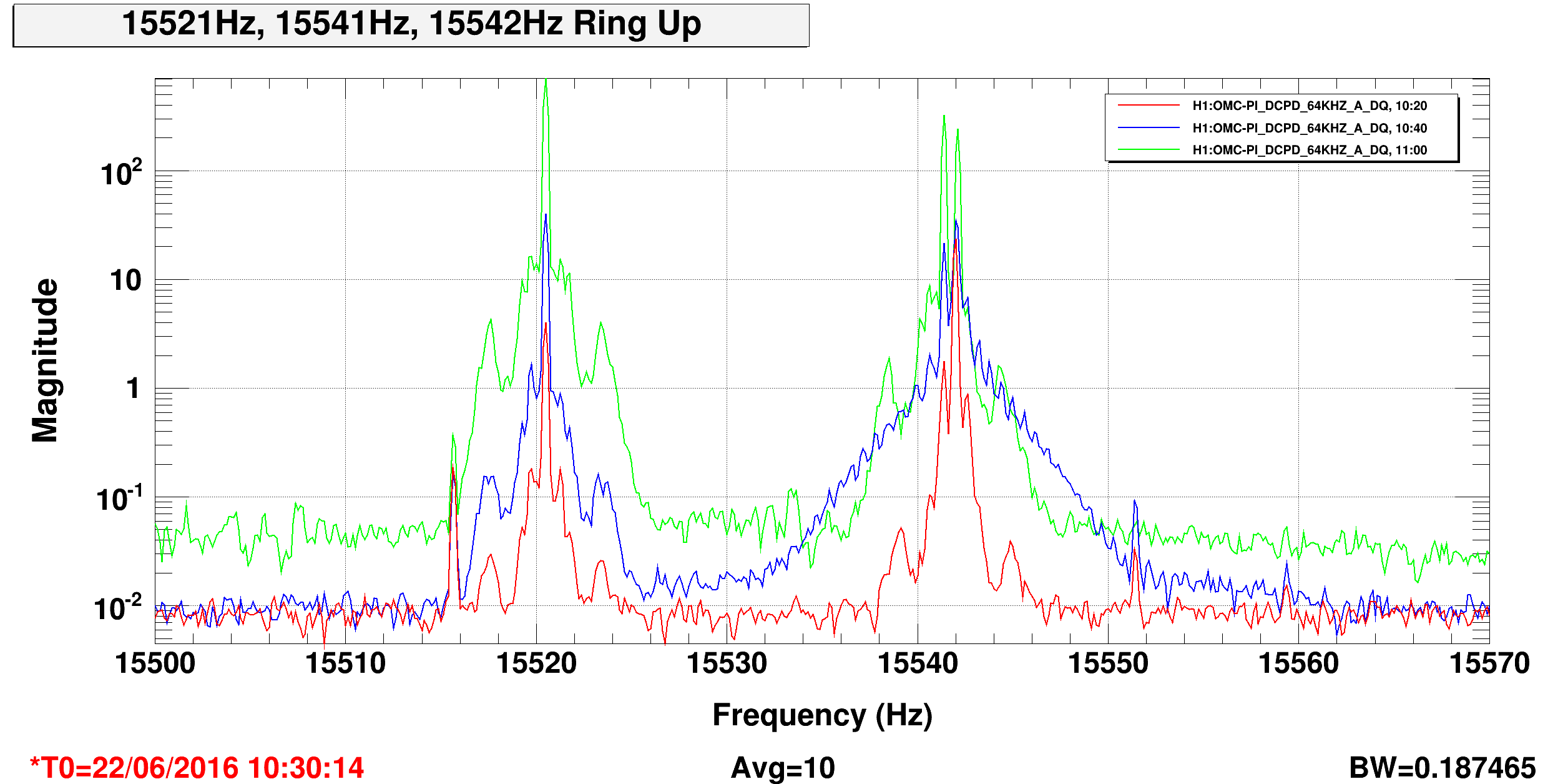
Tonight, 15521 Hz on ITMX was first damped easily but 15541 on ETMX is tricky since we don't have LV ESD on ETMX until further in the locking process. As Sheila mentioned, we tried switching to LV ESD ETMY so I could turn the LV ESD on for ETMX, but had some troubles and ultimately opted to not damp ETMX tonight but rather try remaining < 50 W. By 2 am we were successfully damping ITMX and (preventatively) ETMY ~40 W. A bit before 4am local, 15521 (ITMX), 15542 (ETMY) began ringing up. I'm having trouble grabbing data during these stretches to track the line amplitudes, so here's a spectrum showing the peak amplitude progression (in UTC times). It looks like ITMX led the ring up. Its not clear to me if ETMX went unstable.
We'll need to play with phases and iWave today to see if that helps strengthen damping.
Damping directions (for now) for 15522 of ITMX, 15541 of ETMX, 15542 of ETMY:
1. From orange PI button on sitemap, choose ITMX / ETMX / ETMY --> OMC OVERVIEW --> MODE2 / MODE 1 / MODE 4
2. BP and DAMP filters are populated correctly. DAMP filter gain around saturation with sign - / ? / +
Terra, it is at least theoretically possible to change the ETM LV Driver such that the HV path be active AND an AC coupled LV path (PI) active simultaneously.  It would require some hacking and head scratching, but I don't see that it's impossible at this time.

A high voltage relay selects between the LV mode and the HV mode for each quadrant.  As you know, the HV mode doesn't have much PI drive capability, whereas the LV drive does.  The trick would be to bypass the relay contacts between the LV and HV sides with a high voltage capacitor of 1 to 2nF.  There is a 10k resistor in series with the HV side, so we would tie in on the optic side of the 10k with the bypass capacitor.  Using 1.6nF would put the RC highpass corner at 10kHz, which would slightly reduce the drive amplitude at 10k, so a compromise of corner frequency and PI drive amplitude can be struck.

Let me know, after exhausting other possibilities, whether or not this is worth pursuing.