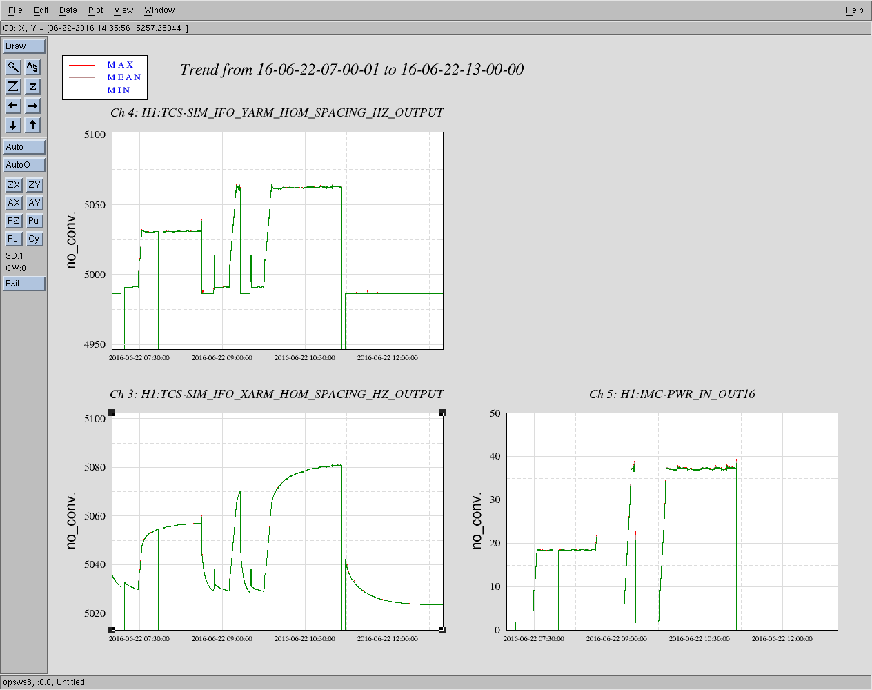
The attached plot shows the arm cavity higher order mode spacing as calculated by Aidan's on-line thermal simulation (TCS_SIM). At 37 W input, the HOM spacing in each arm cavity increases by 60 Hz (X arm) and 75 Hz (Y arm) - relative to the no power-loading case. The ring heater configuration was constant during this time: both cavities had 1 W (total) RH power on the ETM, and no RH power on the ITM. The plot shows that the HOM spacing increases by 30-40 Hz in going from 18 W to 37 W input. If the 15.5 kHz PI modes are stable at 18 W, then we can increase the ETM RH powers to reduce the HOM spacing by 30-40 Hz, and they should then be stable at 37 W. This requires additional RH power of 0.5 W (total, top + bottom).
Couple things to note:
The X-arm simulation output shows a long time constant, but the Y-arm does not. The simulation does include a low pass filter for the surface change due to laser beam self-heating, to simulate this heating time constant. However, this low-pass filter was only engaged for ITMX. I have turned on the filter (surfTF, in FM1) now for all 4 test masses.
The arm cavity power calculation used in the simulation seems to be off. At 37 W input, it is using about 75 kW for both arms, when it should be closer to 150 kW. Something to look into.
Around 20:00 UTC we increased the ring heater power on both ETMs from 0.5 --> 0.75 top and bottom. We've had a few longer locks at 37 W since then and the previously problematic 15.5 kHz peaks have remained low with the RH power increase. Eventually we were able to turn off all active damping and still no sign of PI.
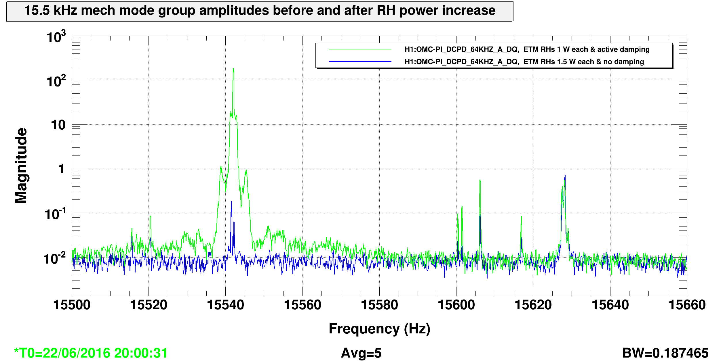
Power spectrum below shows the 15.5 kHz mode group as seen in the OMC DCPDs before RH increase kicking in and after RH increase. Note that in the before state, we were also actively damping with the ESDs. In the after state, we were not actively damping.