Stefan, Kiwamu,
With Keita's instruction in hand (27931), we have closed the 2nd and 3rd ISS loops at the same time. We confirmed that the 3rd loop still suppresses the arm transmission signals.
A next challenge will be to power up the PSL power with both loops closed.
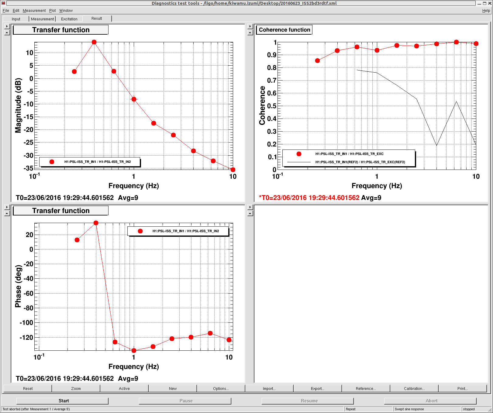
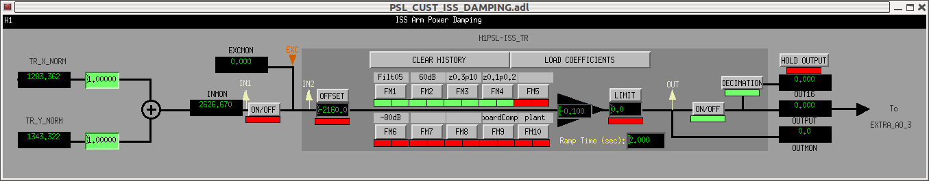
The first attachment is a measured transfer function of the 3rd loop when the 2nd loop was closed. The PSL was set to 20 W. Note that we accidentally had a wrong sign for the control gain in this measurement, so the phase should be read with an extra 180 deg added. As expected the transfer function looks identical to what Keita measured before without the 2nd loop (27898). The second attachment shows the setting we used to close the 3rd loop. As suggested by Keita, we took out FM9. A good gain was found to be 60 dB larger than it was for the 3rd-loop-only configuration. The sign of the gain needed to be negative. We tried closing the 2nd and 3rd loops twice today, one time without an issue, the other time we unlocked the interferometer seemingly due to DAC saturation for the 3rd loop. Once the loop is closed the DAC counts for the 3rd loop is roughly 1000 cnts level -- no problem at all from the range perspective so far.
We then did one quick test where we stepped up the PSL power just by 1 W (i.e. 20 -> 21 W) to see how the ISS system reacts against it. This unlocked the interferometer; seemingly the second loop unlocked first by hitting the trigger upper threshold which subsequently unlocked the first loop whose diffraction power went up to 40 % on a time scale of a couple of seconds.
In alog 27931 I forgot to take into account the 2nd board DC gain of 350 when injecting into 1st loop board. With this correction, the gain at 25W should be 1750 (not 5) with -80dB on, so it's understandable that we need to turn -80dB off and set the gain to 0.1.
I don't understand the sign, maybe the polarity of the PD+whitening of the second loop array is different from that of the first loop PD.