peter.king@LIGO.ORG - posted 11:09, Thursday 07 July 2016 (28226)
FSS transfer functions
Attached are plots of the transfer functions measured this morning. The input modecleaner
was disabled whilst these measurements were obtained.
Note the frequency servo schematic is D040105
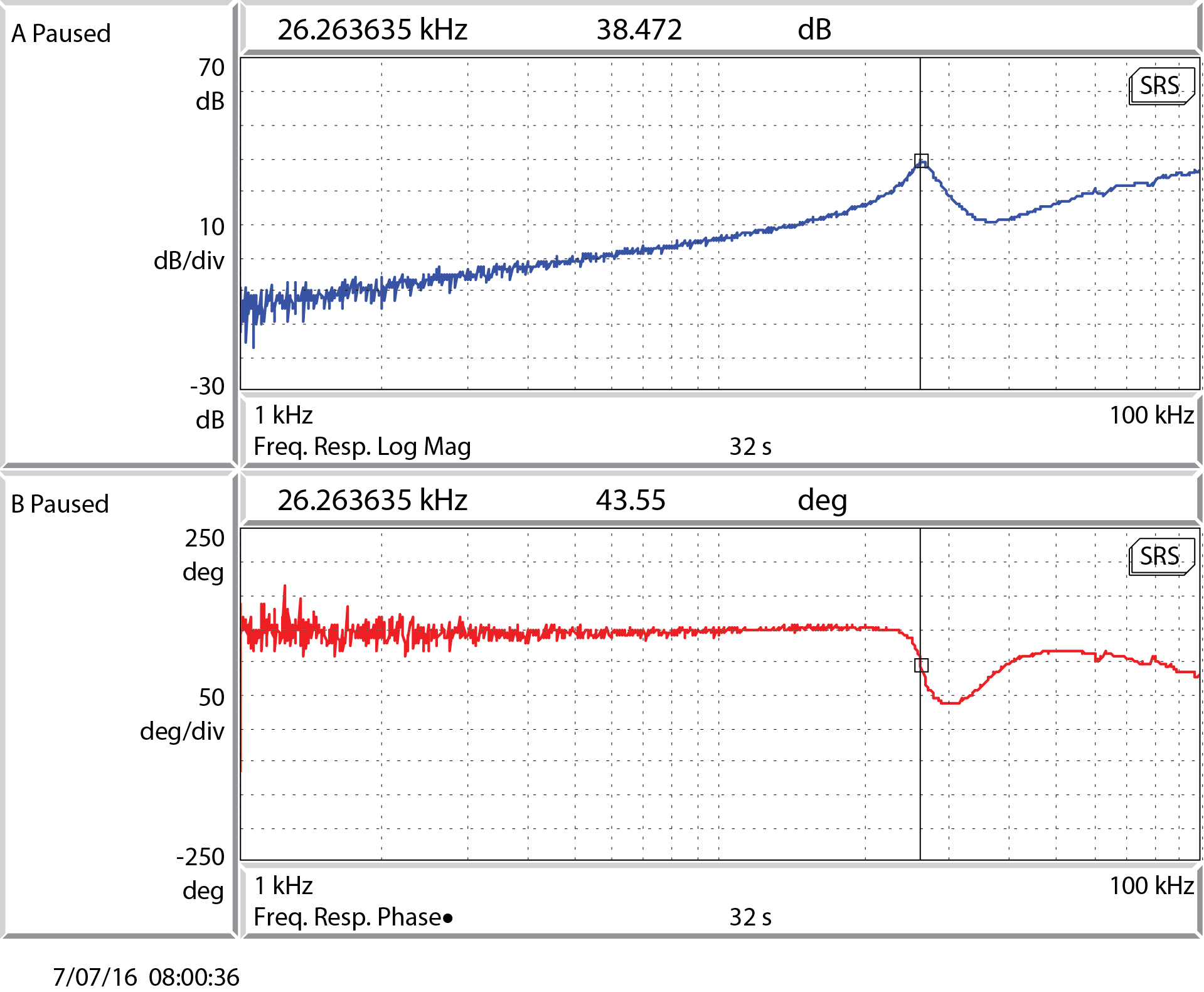
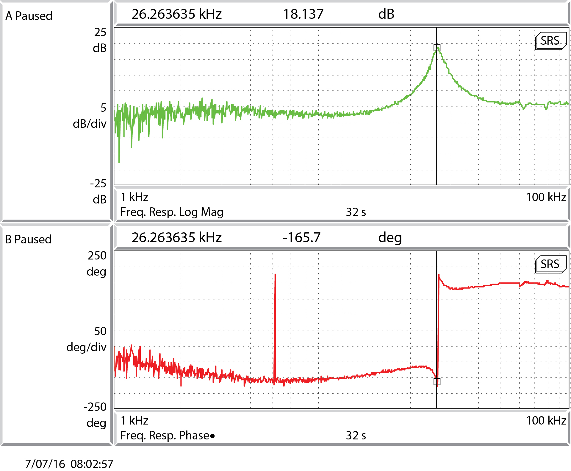
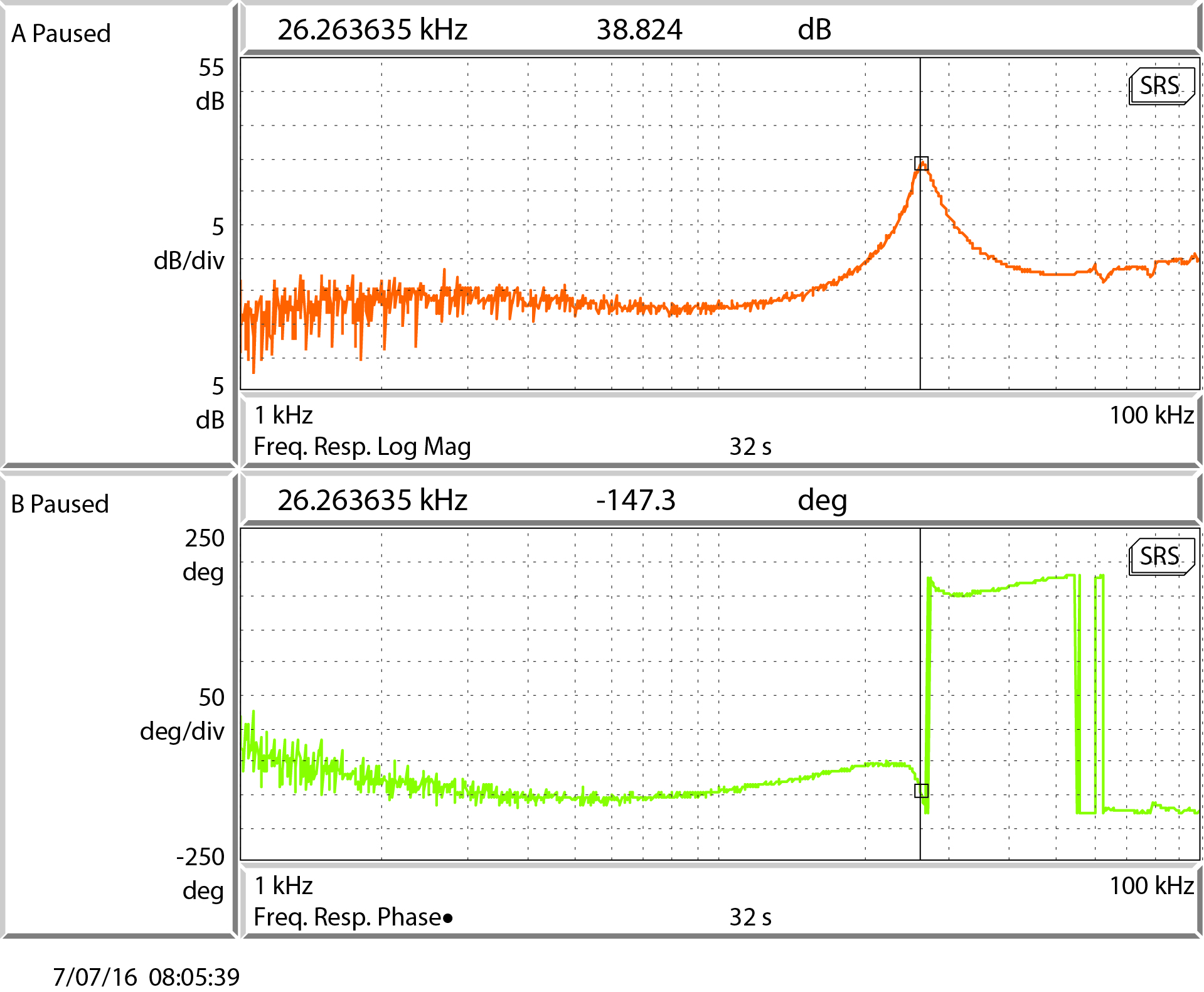
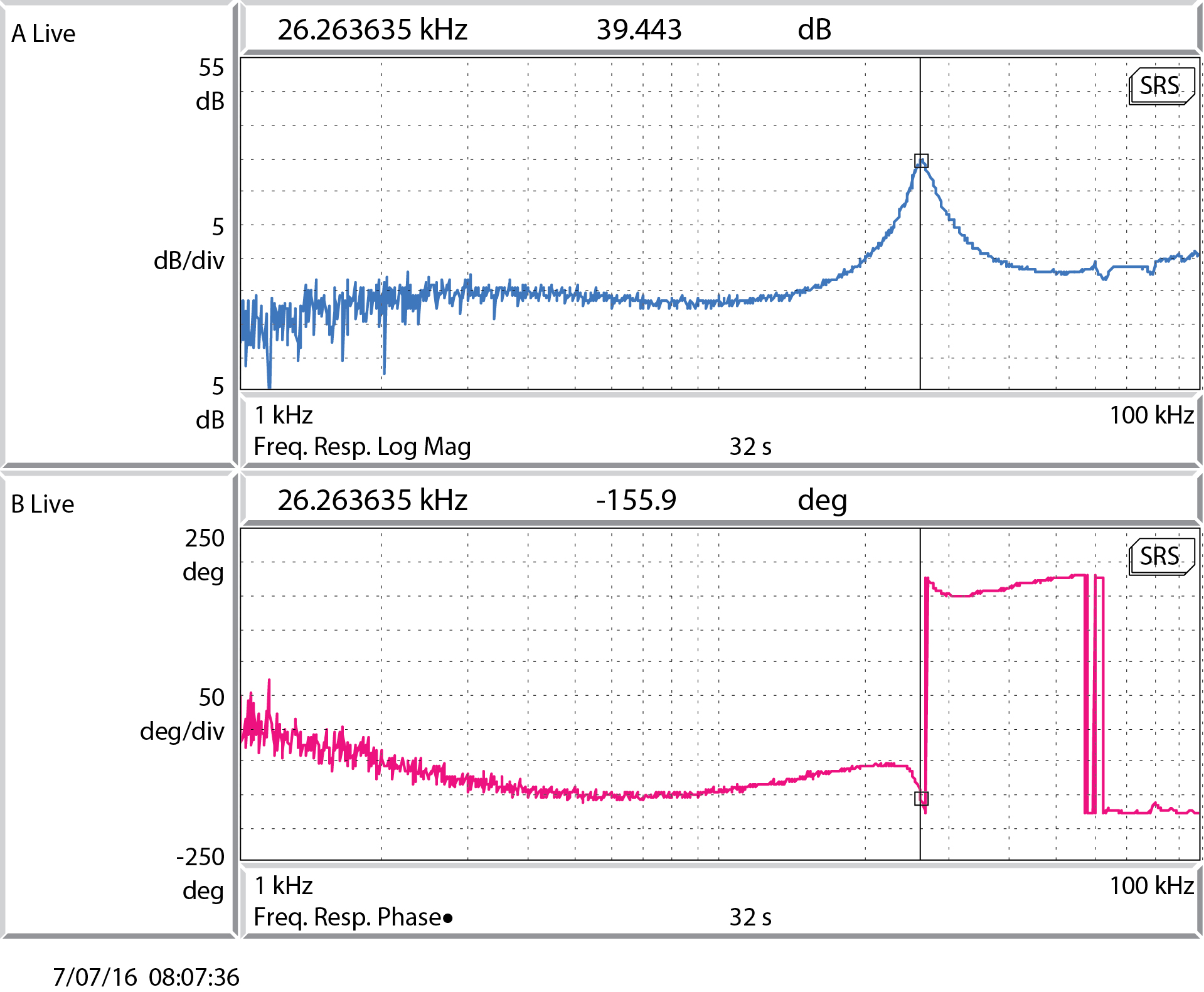
C20F22-1.tif: common gain = 20 dB, fast gain = 22 dB
C20F16-1.tif: common gain = 20 dB, fast gain = 16 dB
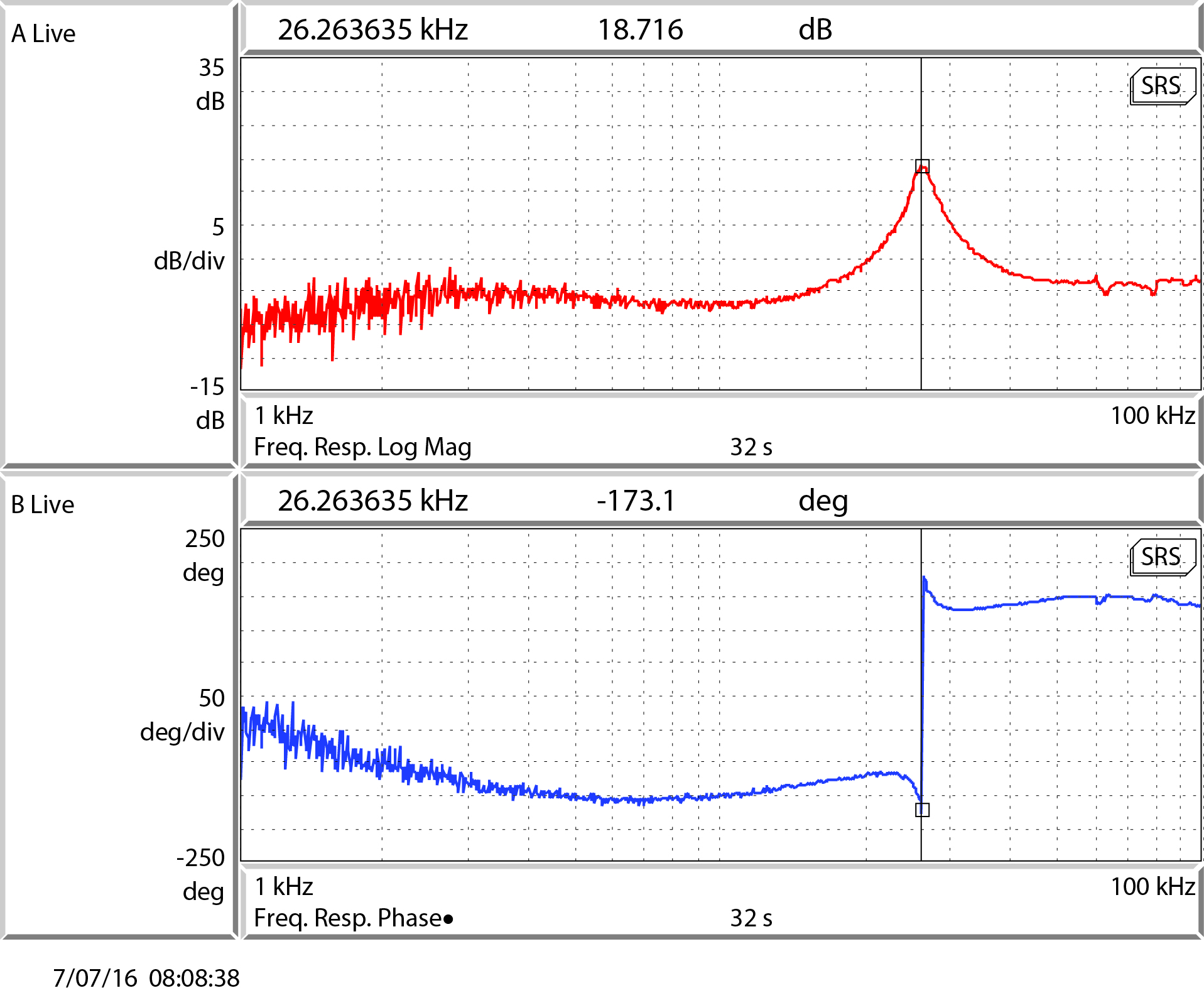
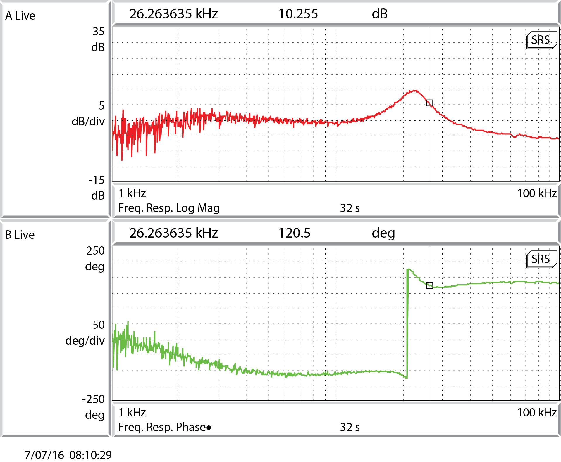
C20F22FastMon.jpg: transfer function measured at TP10
C20F22PCMon.jpg: transfer function measured at TP9
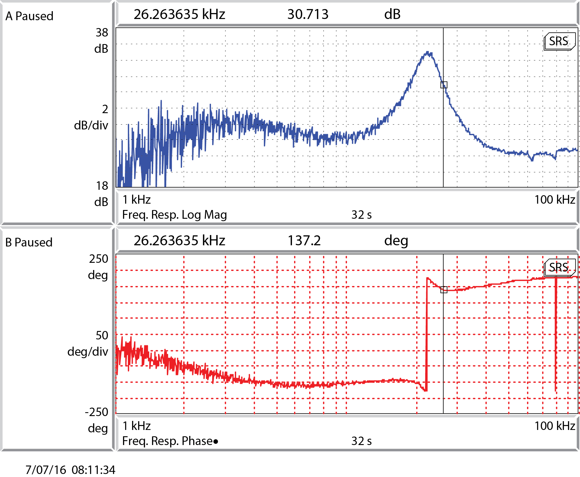
C20F22TP8.jpg: transfer function measured at TP8 (should be 10X greater than TP9 measurement)
common gain = 20 dB, fast gain = 22 dB
C16F22TP8.jpg: transfer function measured at TP8, common gain = 20 dB, fast gain = 22 dB
C16F22TP9.jpg: transfer function measured at TP9, common gain = 20 dB, fast gain = 22 dB
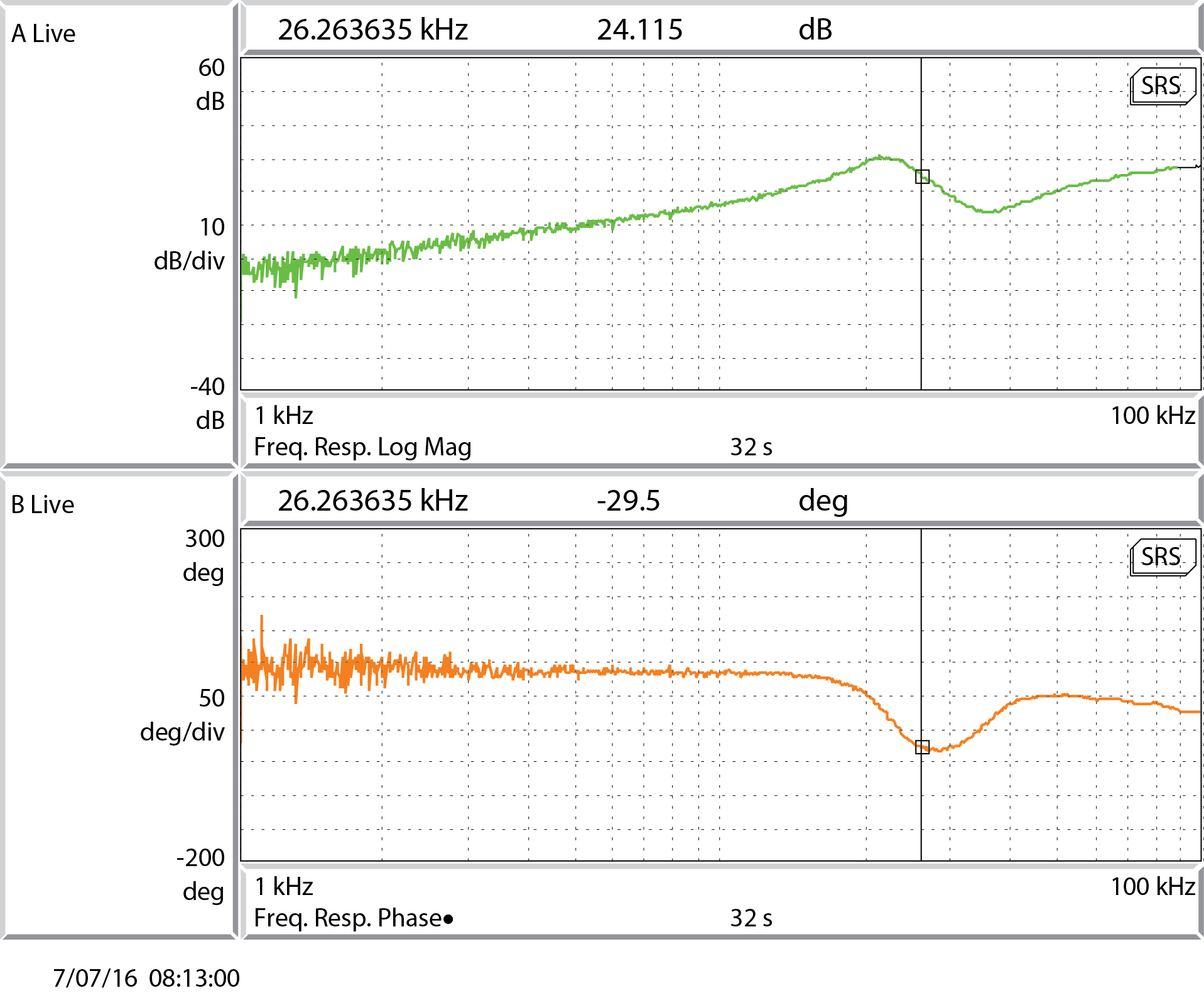
C20F16TP9.jpg: transfer function measured at TP9, common gain = 20 dB, fast gain = 16 dB
C20F16TP8.jpg: transfer function measured at TP8, common gain = 20 dB, fast gain = 16 dB
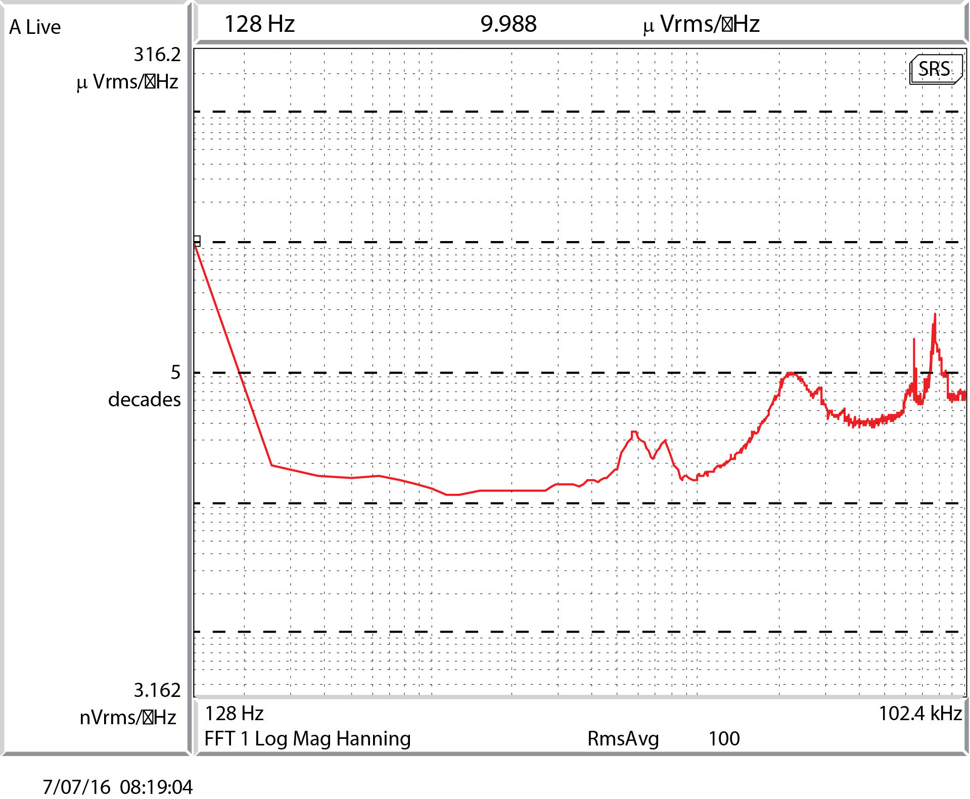
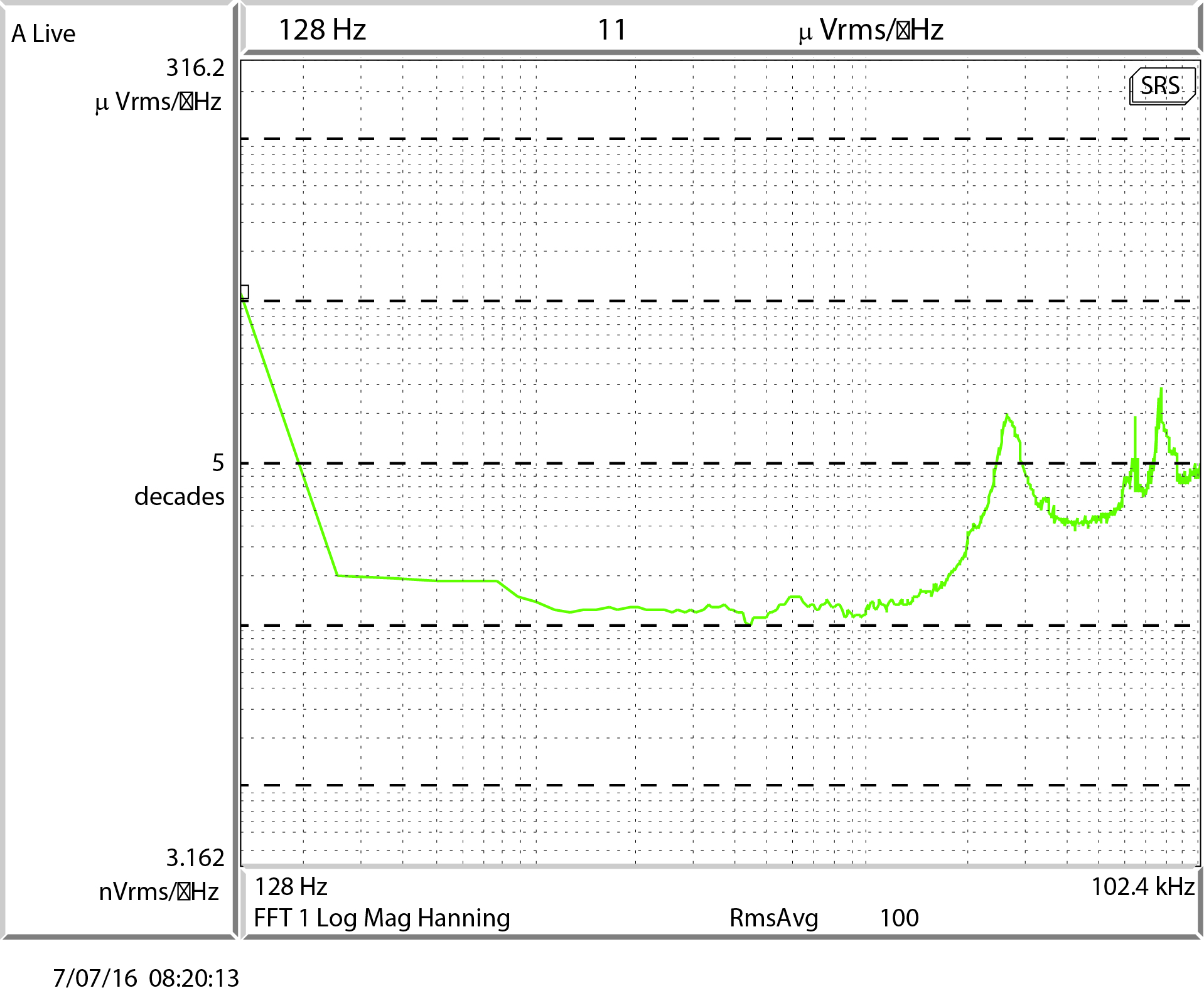
C20F16TP3Spectrum.jpg: noise measured at TP3 (the mixer monitor, or error point)
common gain = 20 dB, fast gain = 16 dB
C20F22TP3Spectrum.jpg: noise measured at TP3, common gain = 20 dB, fast gain = 22 dB
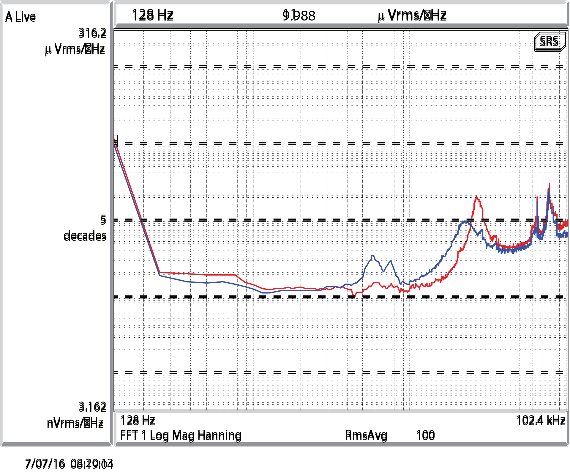
CrossoverSpectrum.jpg: has the two noise spectra overlapped for a visual comparison.
Images attached to this report