carl.blair@LIGO.ORG - posted 00:08, Friday 08 July 2016 - last comment - 14:59, Friday 08 July 2016(28259)
Summary 47.5kHz Instabilities
[Ross, Carl]
This is a summary of what we know about the 47.5kHz instabilities at present.
There are two modes whose aplitudes rise significantly during most locks, they appear in the 65536kSa/sec HF OMC transmission signals at approximately 18038Hz and 18056Hz.
As reported in alog28088 they appear to be super-nyquist ETMY modes that are aliased from 47497Hz and 47480Hz.
They caused lockloss several times when we had increased the ETMY ring heater in an attempt to split the15042Hz ETMX and ETMY modes that are problematic to damp. They have also caused several lock losses over the last day. However there has been a large transient in amplitude for several weeks. Currently when we survive these modes it is by fast thermal transient through a large parametric gain regime. If the transient is fast enough we do not spend enough time in the transient for the mode amplitude to grow to a level to unlock the interferometer. Example amplitude transients can be found here.
The phase of the arm transmission QPDs quadrants relative to the OMC transmission signal was measured for the 18038 Hz mode to be ETMX_A UL 21.7 deg, LL -171deg, UR -129deg and LR 83deg and ETMY_A UL 67 deg, LL -141deg, UR -129deg and LR 66 deg indicating a 'pringle' type optical mode. For reference the 15542Hz vertical mode phase is ETMY UL -178 deg, LL 33deg, UR -163deg and LR 6.5 deg. The pringle shape is the expected shape of a HG11 which has a resonance at approximately 47500Hz in a single arm cavity.
The Q has been estimated as 5.7 million from a ring down time constant of 38.3 sec. This was done at 40W and the parametric gain was not estimated so this number is an upper limit.
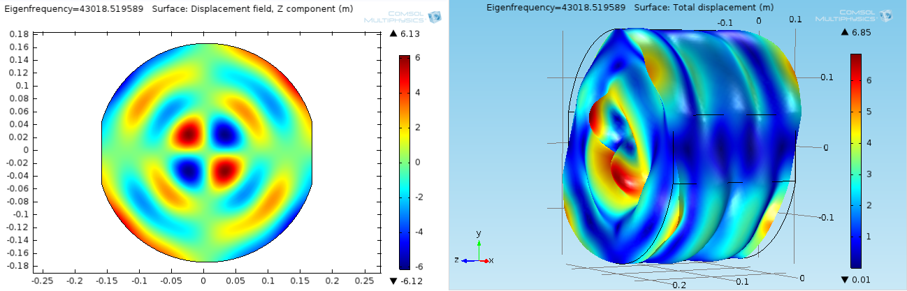
My simulations of the test mass do not show me any very likely culprit resonant modes in a 1kHz band around the observed resonance frequency, many would interact with significant beam decentering but Marie's measurements do not indicate any particular ETMY decentering (to explain only seeing ETMY instabilities). It appears the ears interact significantly at these frequencies. See the mode shape animations with and without ears. The most likely in the group of modes in these animations appears to be the 47942Hz without ears. With ears all modes look like they need some decentering to get significant overlap. However there is a suspicious mode at 43kHz (separate image). I am not confident in the simulation at these frequencies, we need more high frequency mode identification to increase confidence in the model.
The mode has now been excited and damped and the damping setting have been put into the SUS_PI guardian. The current damping settings use the OMC HF signal down-converted on 17300Hz transmitted to the end station then up-converted. The signal then passes through a 10Hz wide band-pass filter -30deg phase and -3000 control gain driving the LL quadrant. The phase response of the 10Hz wide bandpass may not be adequate as this mode is likely to shift more than 1 Hz in the thermal transient, while the filters response is approximately 60 degrees per Hz. The filter used is a normalised combination of cheby2, butter and a notch to reduce the phase gradient.
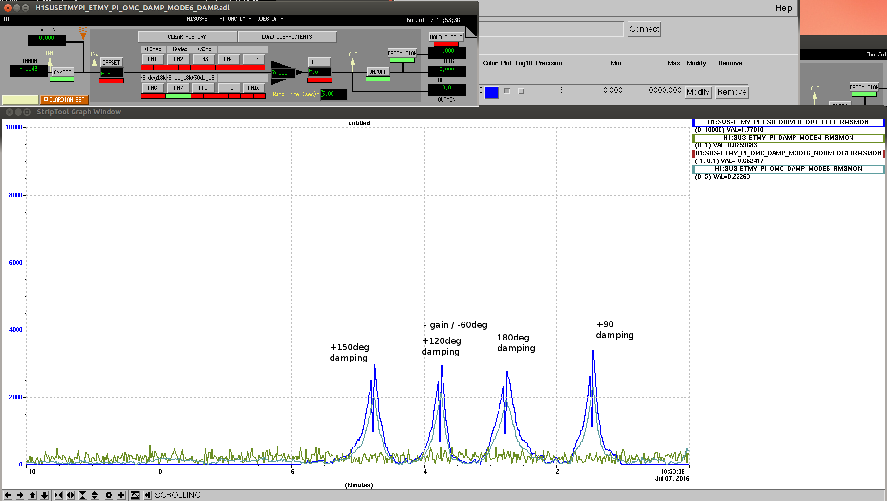
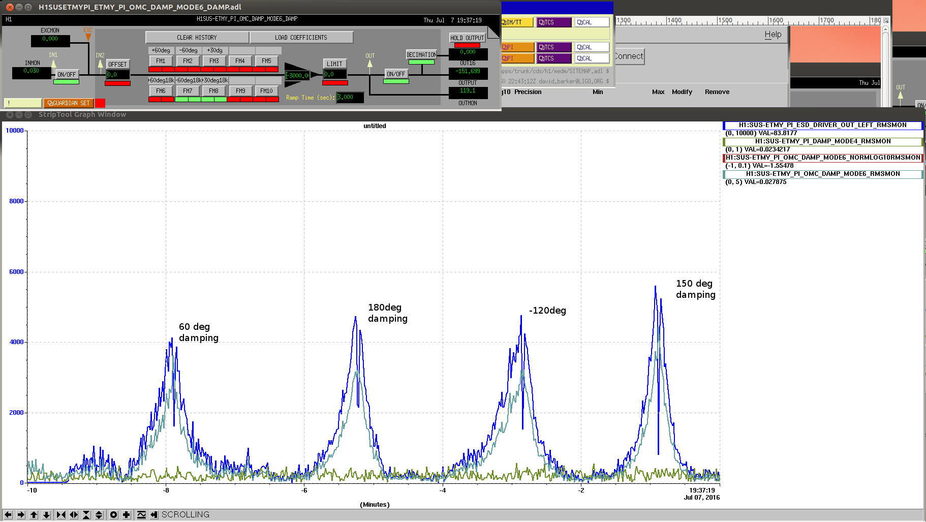
A narrow filter was compared to a wide filter when doing the phase optimisation. There are 2 lines within +/-5Hz. These lines beat and the result is a reduction the 'effective damping strength'. The two plots show the phase optimisation with the narrow filter and the broad filter. The optimums were found to be 150 deg (broad) and +90deg (narrow). In this case the cost of the beat signal is a factor of ## reduction in the effective drive strength.
A narrow filter (2Hz) was compared to a wide (10Hz) filter when doing the phase optimisation. There are 2 lines within +/-5Hz. These lines are removed by the narrow filter but not by the wide filter, resulting in a reduction of the 'effective damping strength'. The two last plots show the phase optimisation with the narrow filter and the broad filter. The optimums were found to be 150 deg (wide) and +90deg (narrow). In this case the cost of the beat signal is a factor of 2 reduction in the effective drive strength going from a damping time constant of 4.4 seconds (narrow) to 9 seconds (wide) at the optimum damping phase (with the same control gain and filter normalisation on resonance).
A narrow filter was compared to a wide filter when doing the phase optimisation. There are 2 lines within +/-5Hz. These lines beat and the result is a reduction the 'effective damping strength'. The two plots show the phase optimisation with the narrow filter and the broad filter. [Ross, Carl]
This is a summary of what we know about the 47kHz instabilities at present.
There are two modes whose alpitudes rise significantly during most locks, they appear in the 65536kSa/sec HF OMC transmission signals at approximately 18038Hz and 18056Hz.
As reported in alog @@@ they appear to be super-nyquist modes that are aliased from 47333 47333.
They caused the interferometer to unlock several times when we had increased the ETMY ring heater in an attempt to split the 15042Hz ETMX and ETMY modes that are problematic to damp. They have also caused several lock losses over the last day where the interferometer was being locked from a cold state. Currently when we survive these modes it is by fast thermal tranisent through a large parametric gain regime. If the transient is fast enough we do not spend enough time in the transient for the mode amplitude to grow to a level to unlock the interferometer.
The phase of the arm transmission QPDs relative to the OMC transmission signal was measured for the 18039 Hz mode to be ETMX UL 21.7 deg, LL -171deg, UR -129deg and LR 83deg and ETMY UL 67 deg, LL -141deg, UR -129deg and LR 66 deg indicating a 'pringle' type optical mode. For reference the 15542Hz vertical mode phase is ETMY UL -178 deg, LL 33deg, UR -163deg and LR 6.5 deg. The pringle shapes is the expected shape of a HG11, which has a resonance at approximately 47500Hz in a single arm cavity.
The Q has been estimated as 5.7 million from a ring down time constant of 38.3 sec. This was done at 40W and the parametric gain was not estimated.
My simulations of the test mass do not show me any very likely culprit resonant modes in a 1kHz band around the observed resonance frequency. It appears the ears interact significantly at these frequencies. See the mode shape animations with and without ears. The most likely in the group of modes in tha animation appears to be the 47942Hz. However there is a suspicious mode at 43kHz. I am not confident in the COMSOL simulation at these frequencies, we need more high frequency mode identification to increase confidence in the model.
The mode has now been excited and damped and the damping setting have been put into the SUS_PI guardian. The current damping settings use the OMC HF signal downconverted on 17300 transmitted to the end station then upconverted. The signal then passes through a 10Hz wide bandpass filter -30deg phase and -3000 control gain driving the LL quadrant. The phase response of the 10Hz wide bandpass may not be adequate as this mode is likely to shift more than 1 Hz in the thermal transient, while the filters response is approximately 60 degrees per Hz. The filter used is a normalised combination of cheby2, butter and a notch to reduce the phase gradient.
A narrow filter was compared to a wide filter when doing the phase optimisation. There are 2 lines within +/-5Hz. These lines beat and the result is a reduction the 'effective damping strength'. The two plots show the phase optimisation with the narrow filter and the broad filter.
Images attached to this report
Comments related to this report
The phase of the 18040Hz mode flipped during this lock stretch. The damping has been switched to the arm transmission QPDs gain 10,000 phase + 60 deg.
The 18056Hz mode also became unstable and was succesffully damped with settings in SUS_PI guardian.
The ETMX 15541.8Hz mode and ETMY 15542.6Hz modes that have been difficult to damp were damped well tonight with the arm tranmssion QPD signals. The rational was that the arm transmission QPD's differentiate the arm the mode is in to some extent reducing the beat effect. These settings are in the SUS_PI guardian. The revert comment out the ETM QPD gain settings and uncomment the OMC gain settings for these modes.
Carl - I'm wondering if the width and apparent double nature of each mode could be due to the same mode being excited in
the coating-bearing mass and in the reaction mass - could the reaction mass body modes be getting rung up as well? Just a thought.
Might be nonsense.