carl.blair@LIGO.ORG - posted 19:15, Sunday 17 July 2016 (28462)
Proposed PI damping architecture
[Matt, Daniel, Carl]
We have a proposal for a new parametric instability damping architecture that provides several advantages over the previous design.
The key differences are:
> All error signals are down-converted to 2kSa/sec channels for processing.
> Line tracking (iwave of PLL) is done in a new slow corner station model running a 2kSa/sec.
> The signals being sent from the corner to the ETMs are processed control signals for damping at the ETMs (rather than the raw OMC_HF signal).
> The fast sus models up-convert and combine the 2kSa/sec channels to reconstruct the 64kSa/sec control signal.
The advantages are:
> With line tracking done in a slower model more modes can be tracked per core.
> As all the error signals are in the same place linear combinations of error signals can be generated for all test masses. These linear combinations may be used to subtract for example the ETMX 15541Hz component from an ETMY 15542Hz control signal. (The error signals on the QPDs are larger in the arm where the mode is present, however we need to work out a way to get the phase correct) > The design is easier to upgrade in the case that more instabilities arise at higher power by adding additional processing cores in the corner station.
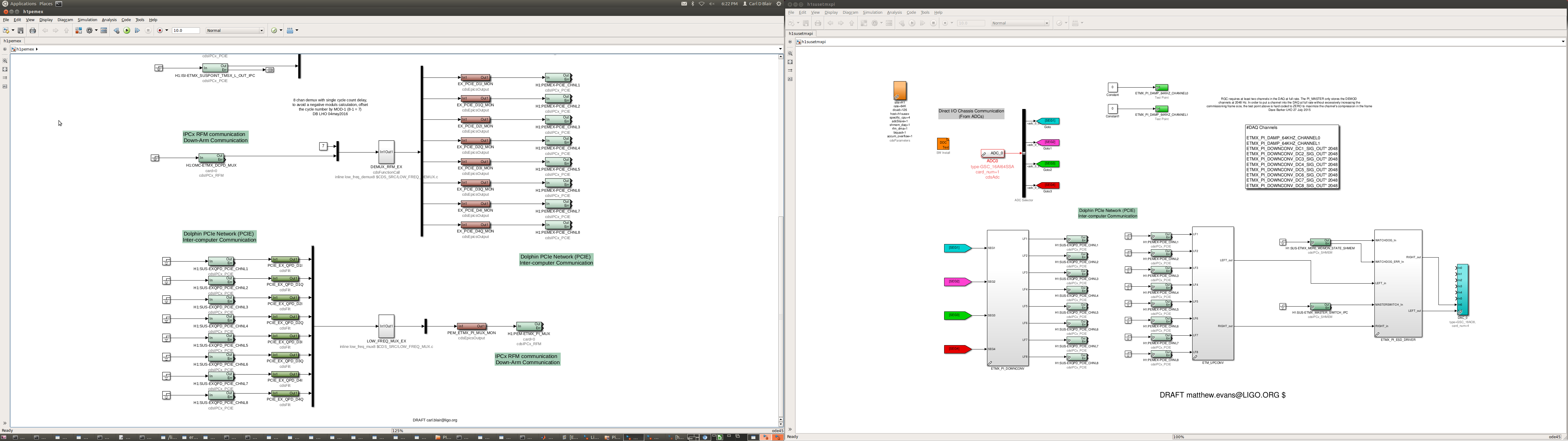
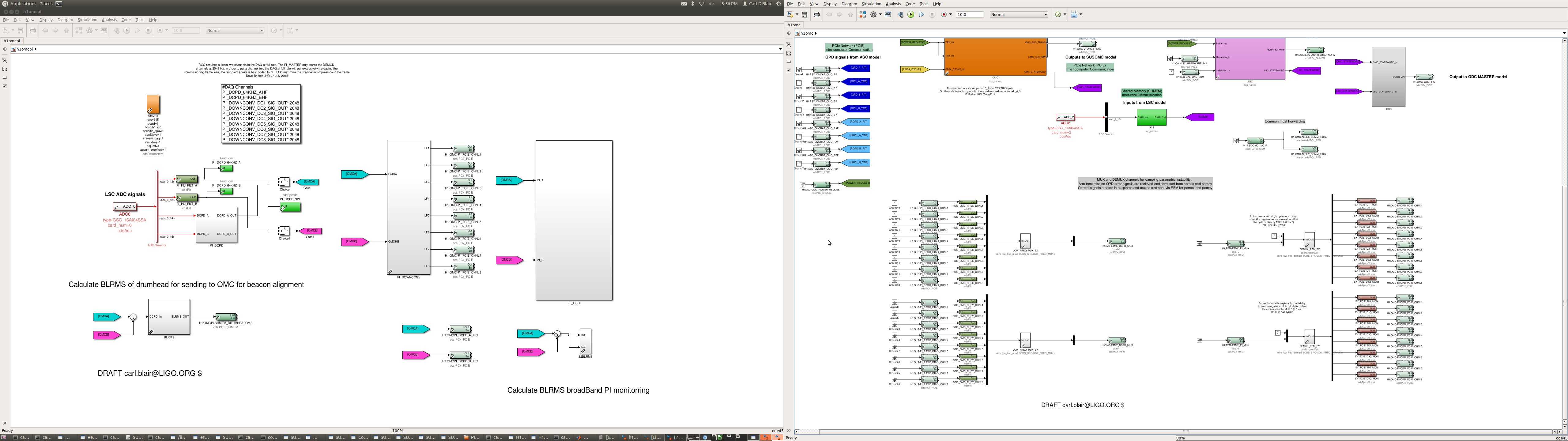
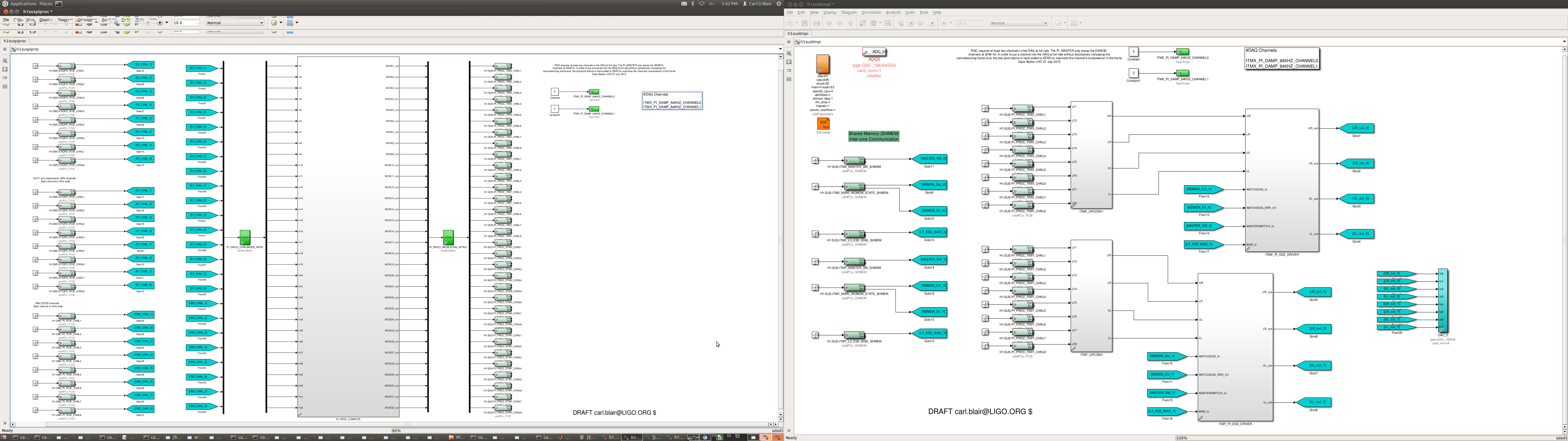
The flow diagram shows the signal path ith the proposed model in teh grey model boxes.
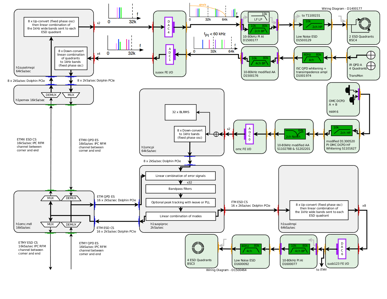
There are three sources of error and monitoring signals. The OMC DCPD HF path and the two arm transmission QPDs (only one is drawn for brevity). Skipping over the analogue (green) parts, I will describe the digital signal processing chain (grey). The QPD signals are down-converted, then passed to the h1pem end station models to be multiplexed onto 16kSa/sec RFM channels. h1omc receives these RFM channels and de-multiplexes them and passes them to the new processing model (h1suspiproc) that will run on the oaf0 computer. h1omcpi passes the DCPD HF error signal to the processing model via dolphin. The processing computer uses a matrix to make linear combinations of channels. Then it has a block of 32 band-pass filters and optional tracking blocks. Finally a matrix is used to create he linear combination of modes that get sent out to each test mass's set of control signal channels. ITM channels are sent via dolphin and the ETM channels reverse the path described the the error signals. BLRMs channels in the fast h1omcpi model monitor for unknown unstable modes.
Matt and I built draft models yesterday. The models mostly use current PI library parts. The top level diagrams are attached.
Images attached to this report