[Matt, Carl]
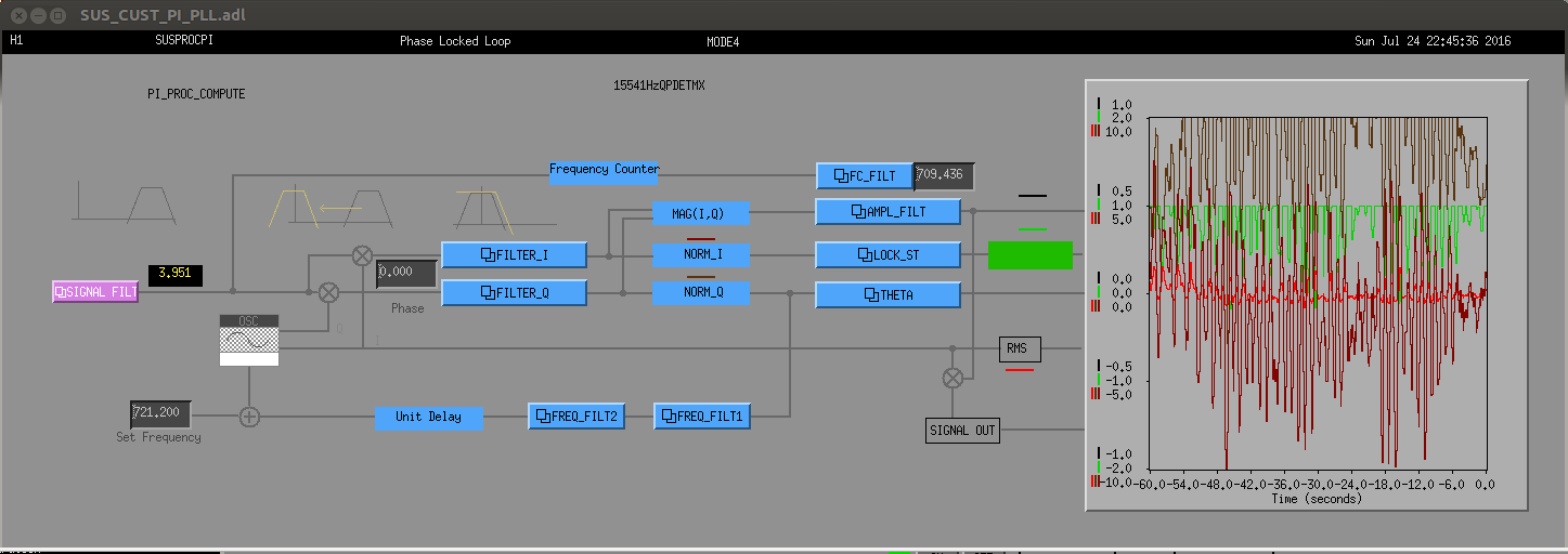
The phase lock loop is now installed as an optional tool in the PI armory. I have used the settings and method Matt demonstrated to me on the test stand to lock onto OMC PI signals in the last 50W lock. I tried locking onto QPD signals but was unable to at quiescent amplitudes. The phase locked loop in the locked state is shown in the first image. It is tracking a 15521Hz ITMX mode (sorry for the poor labeling in the figure, there's still a few bugs in medm screens).
The settings used were:
Filter I - 100Hz LP Gain 1
Filter Q - 100Hz LP Gain 1
Freq Filter 1 - gain 1
Freq Filter 2 – gain 0.02, 20mHz integrator + low pass see below
FC Count - 10mHz low pass (this was not low enough as the frequency estimate was still fluctuating by 20Hz
Ampl Filt er - 1Hz low pass gain 1
Lock Filter - 1Hz low pass gain 1
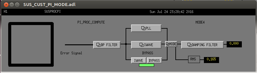
Lock was acquired by setting a set frequency close to the mode frequency observed in a spectrum of the OMC HF channels. The loop was engaged with a 100Hz low-pass in Freq Filter 2 then put in a narrow band mode by engaging a 1Hz low-pass in Freq Filter 2, the loop lost lock when I tried to further reduce its bandwidth by either reducing the gain of decreasing the frequency of the low-pass. The figure is in the high bandwidth mode. The PLL and iwave can be accessed from the mode block for any mode and a matrix is used to select a control signal, see the second image.
I think the best way to transition from PLL "aquisition mode" (high-gain and wide-band) is:
- start with gain of 1 in FREQ_FILT1 and 2 (FF1 and FF2), no filtering in FF1, and LP10 in FF1
- lower the gain in FF1 to ~0.02
- engage a low-pass filter in FF1 (e.g., LP0.1)
This should keep the output of FF2 (which contains an integrator) fairly constant, and thus keep the PLL locked during the transition.
Well, step 1 was supposed to read:
start with gain of 1 in FREQ_FILT1 and FREQ_FILT2 (FF1 and FF2), no filtering in FF1, and Int20mHz + LP10 in FF2