This is a follow up of this alog entry I promised and forgot to write.
Current status:
The first segment of IR QPD 2 is short-circuited (alog by Filiberto, though the entry doesn't say "short circuit") (D1002283 to see which pin is which) and the ADC for this segment is railed at -32k counts.
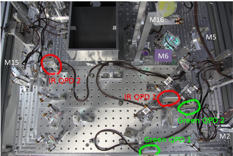
Using flood light on the floor as the light source, Dan Hoak confirmed that QPD 2 is the one closer to the ETM (see attached picture), as it's supposed to be.
Though this is another story, actually QPD2 signals appear in QPD A channels in digital world, which doesn't make sense. I've confirmed that QPD A takes channels 0 to 3 and QPD B 4 to 7 on ADC0, so this is not a model issue. Probably DB9 part of DB25 to 2xDB9 interface cable for QPDs (D1101801) were swapped in the trans impedance amplifier box (D1002481), and I asked Richard to have somebody look at it.
How it happened:
Three of four in-vacuum ISC cables were connected to wrong feedthroughs (https://alog.ligo-wa.caltech.edu/aLOG/index.php?callRep=2561) though people didn't realize that it's all wong: IR QPD cable to picomotor port, picomotor cable to beam diverter port, and beam diverter cable to IR QPD port. The only correct one was green QPD.
If you payed attention to the above alog, it would have been obvious (see D1003085, flange layout diagram). Unfortunately I was out of town on vacation, read the alog but didn't check, and when I was back I totally forgot. Shame on me.
In-air cabling was done "correctly".
On May/08/2012 we attempted to move one of the picomotors, and high voltage from the picomotor driver hit the QPD.
What will happen:
It will stay for the H2 one arm test, and we'll fix it when we move TMS to H1.
aLIGO integration issue tracker system is perfect for remembering this kind of stuff. This specific issue is found here: https://services.ligo-wa.caltech.edu/integrationissues/show_bug.cgi?id=1
Other thoughs:
Always laminate flange layout diagrams (like D1003085) and cable routing diagrams (like D1101478), wipe and bring them in chamber when making in-chamber connections.
It would be nice if the flange numbers (FC1, FC2 etc.) and the subflange numbers (1C2, 3C1 etc.) are stamped or scribed somewhere in chamber.
But the most important thing is, don't forget to check things. Have more than one person check this.
Looked at cabling inside ISC QPD Transimpedance Amp Chassis (D1002481). No issues. Followed cabling going to ISC Whitening Chassis (D1002559). No issues. Cabling coming out of ISC Whitening Chassis going to Anti-Aliasing and 384 Channel Acromag Binary Output (D1100251) were not landed correctly. Swapped following cables:
ISC-BSC6-9 with ISC-BSC6-10 (Both DB9).
ISC-BSC6-5 with ISC-BSC6-6 (Both DB37).

Did the same for second ISC Whitening Chassis Unit:
ISC-BSC6-11 with ISC-BSC6-12 (Both DB9).
ISC-BSC6-7 with ISC-BSC6-8 (Both DB37).

Had Dan Hoak look at signals for QPD A and QPD B. Dan said things looked in order. Need to look at green QPD's, to see if they are also correct.

Filiberto Clara