WP 6022
I have updated the PI models (28462) in order to accommodate four excitation paths for test mass' drum head modes. The h1omcpi and h1susprocpi models will be restarted tomorrow. The modification will be used
- as a part of the OMC beacon (or deacon) dither alignment control, and
- as a part of study on the mobility of test mass's mechanical modes.
This update actually involves not only h1omcpi and h1susprocpi models but also h1omc. However, in light of the upcoming in-vac activity with the OMC, we will hold off the update on h1omc so that we can recover the interferometer with least confusion. The update on h1omc will go in some time later once we recover the interferometer.
[eLIGO amplitude locked loop]
Here is a screenshot of the digital amplitude locked loop of a drum head mode that had been used in eLIGO.
This algorithm is imported to the current PI models. One update we might additionally implement in some future is a clock recovery with iWave instead of the clipping-based clock recovery.
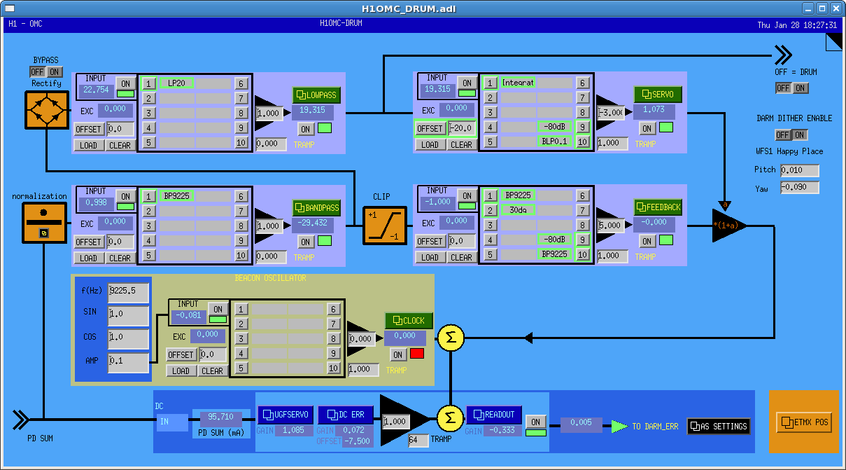
[Modification on h1omcpi]
h1omcpi has one update i.e., normalization of the OMC DC signals.
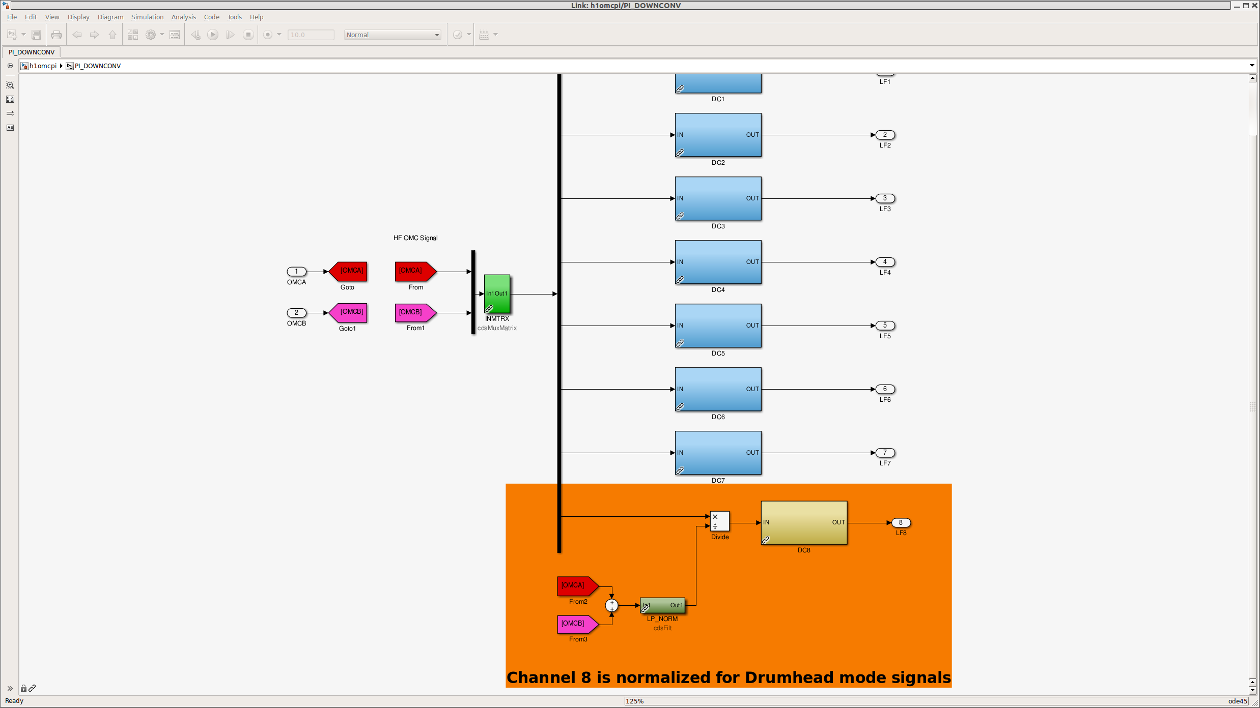
I modified one of the down conversion channels, chan 8, to have a normalization using the OMC DCPD SUM. It is show in the orange-shaded region. This signal is sent to the susprocpi model and processed to generate feedback signals for the test masses.
[Modification on h1susprocpi]
Here is a screenshot of the top level of h1susprocpi in which a parallel excitation block for the drum head modes (a pruple block at the bottom) are shown.
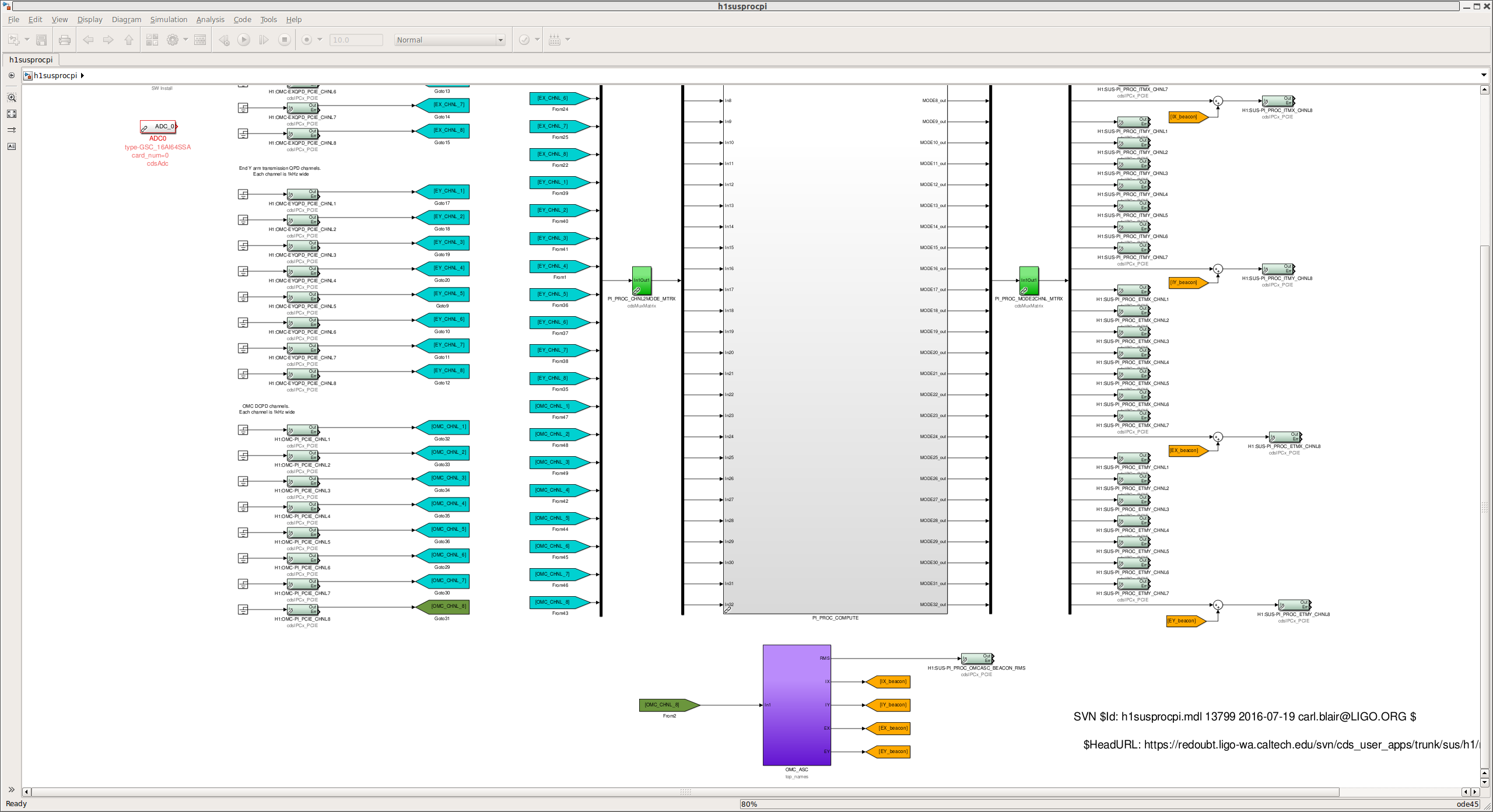
This block contains four identical amplitude locked loop for generating excitation signals. The feedback outputs (shown as yellow tags) are summed on the right hand side of the output matrix so that they are sent to the test mases to excite the drum head modes. Also the rms information of a selected mode will be sent back to h1omc through an PCIe communication so that it can be used as a beacon alignment error signal. The contents of the purple block look like this:
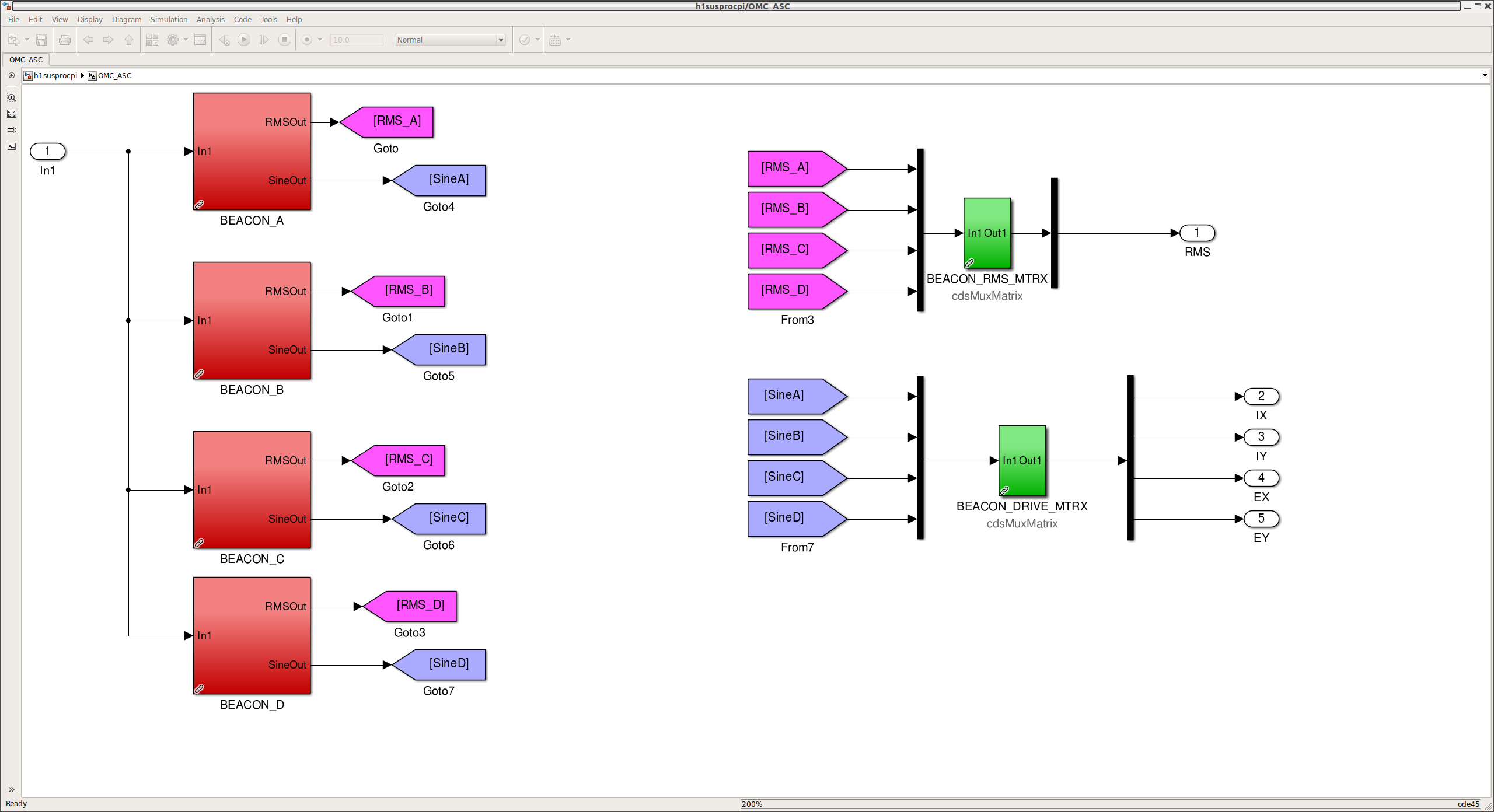
As seen in the upper right, one can select which mode to use for the OMC alignment. The red blocks on the left hand side contain the function blocks as seen in the following screenshot.
![]()
The amplitude error signal is generated by a combination of an Abs block and lowpass filter. Then it is fed back to the output of the clock generator (which is based on the clipping technique as was done in eLIGO). The bandpass filter on the left allows one for selecting a mode out of the four modes. In addition, we placed an iWave block so that we can read out the frequency directly. A future expasion would be to use the output of the iWave block to generate the clock or sinusoidal excitation signal instead of the clipping-based one.
This change has been implemented yesterday (28826).