jeffrey.kissel@LIGO.ORG - posted 18:56, Friday 26 August 2016 (29344)
PUM RMS Watchdog Investigations
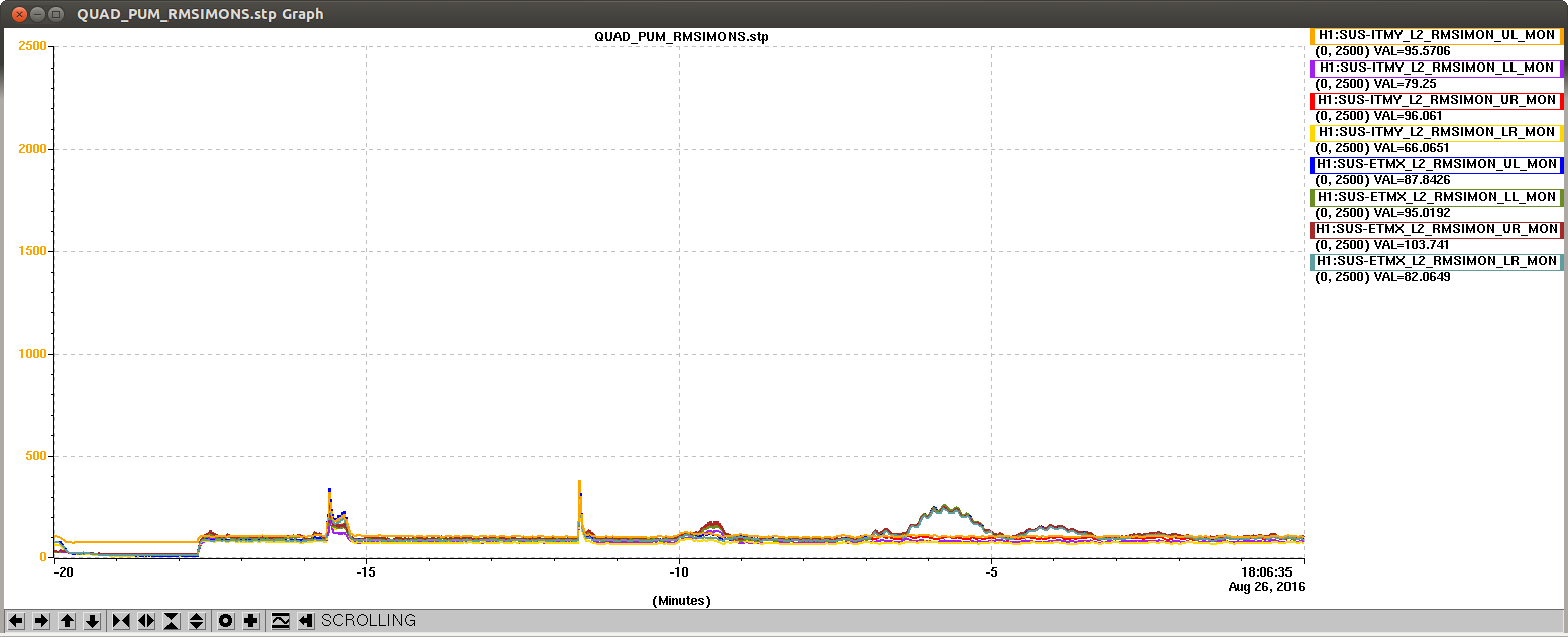
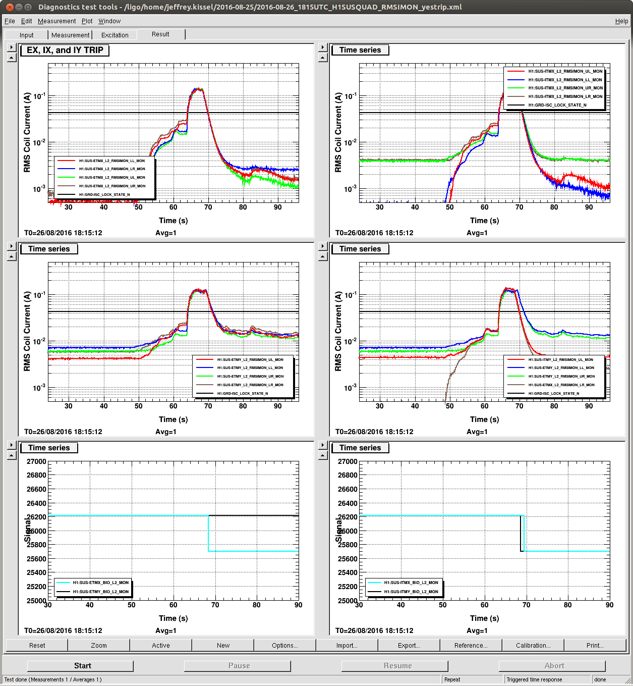
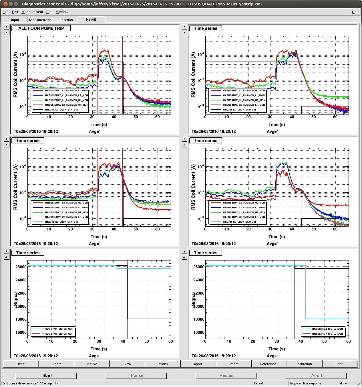
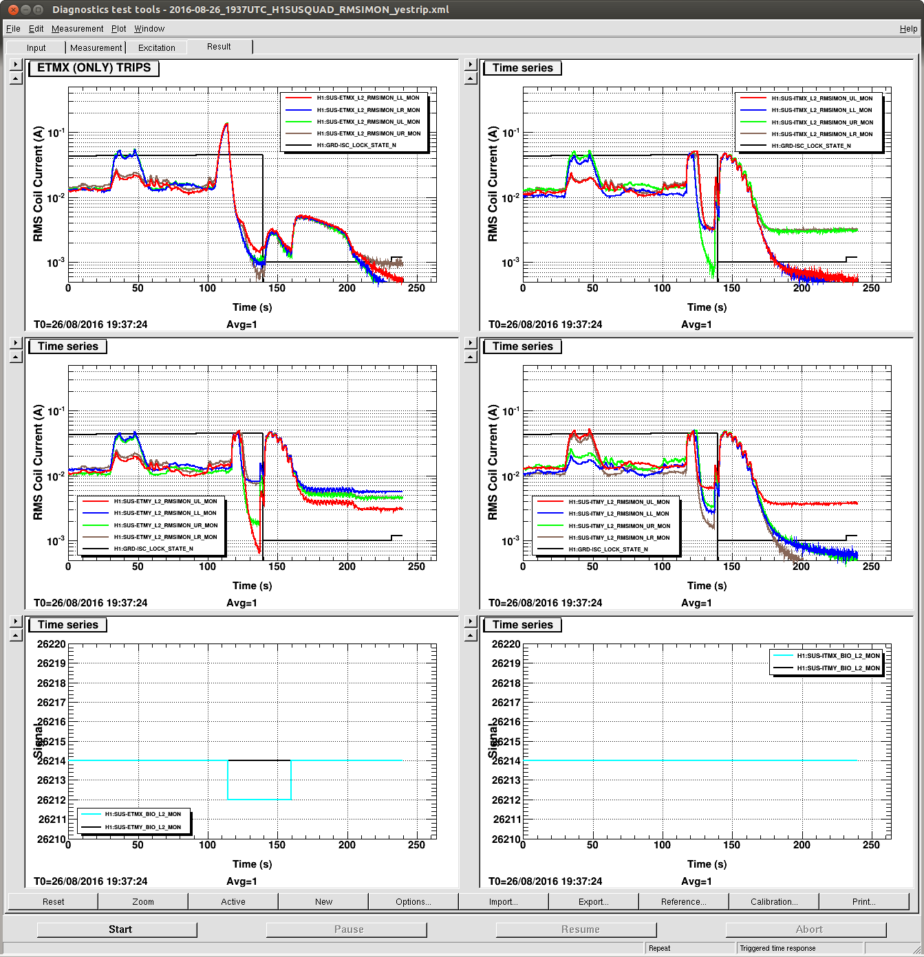
J. Kissel, R. Abbott, D. Coyne, P. Fritschel, V. Sandberg

As a part of the engineering change request to remove/disable the problematic QUAD's PUM driver, RMS current, entirely analog, watchdog (ECR E1600270, and FRS Ticket 6100), I've looked into several of today's episodes of watchdog tripping. I show four examples:
18:15 UTC -- where we ride through an aquisition event where the watchdog surpasses its threshold but does not trip.
19:20 UTC -- A lock loss that we believe is caused by the PUM watchdog tripping
19:37 UTC -- A lock loss caused by watchdog tripping,
01:00 UTC -- A "normal" lock acquisition.
These examples are plotting the time series of the RMS Current Monitor EPICS channels (e.g. H1:SUS-ITMY_L2_RMSIMON_UL_MON), which serves as the trigger signal for the Flip Flop circuit in the driver. Check out pg. 3 of T1100378 for a block diagram, and a more detailed copy-and-paste draw that shows the inter-circuit connections is in D1600332.

From the PUM driver board and monitor board schematics (D070483 and D070480, respectively), with the help of the block diagram, the calibration of these RMS IMON channels is as follows:
RMSIMON [A] = RMSIMON [ct]
              * ADC Gain [V/ct]
              * RMS Input Gain [V/V]
              * RMS Output Gain [V/V]
              * Current Monitor Gain [V/V]
              * Output Impedance [A/V]

            = RMSIMON [ct]
              * 40 [V] / 2^16 [ct]
              * 1 / 10 [V/V]
              * 10 / 1 [V/V]
              * 3/2 [V/V]
              * (1 / 15) [A/V]

            = RMSIMON [ct]
              6.1035e-5 [A/ct]

As is reported in the PUM driver's design study (T0900277), user guide (T0900290), and several test reports (e.g. S1101561), the RMS watchdog level trips at ~100 [mA]. Thus, the attached examples (except for the 18:15 UTC example) works as designed.

The StripTool isn't calibrated but after looking at the raw DTT time series and playing around with the calibration at various points: the voltage going into the Flip Flop circuits that corresponds to ~100 [mA] is ~7 [V] RMS, which is about ~2000 [ct] in the RMS I MONs.

The StripTool for the 01:00 UTC lock acquisition sequence therefore shows that quiescent current levels are a few hundred counts, or a few 10s of [mA] RMS, well below the threshold. The humps and bumps you see are transitions between states as various DARM / QUAD fed ASC loops turn on.

I'll also note, for the record that Jenne installed a low pass filter (aLOG to come later) between the DTT measurements and the StripTool, so we may be OK again. Maybe the watchdog being problematic every few months is because that's about the timescale in which we usually overhaul our ASC schemes, and the trips are just indicative of transitionary, mid-commissioning, loop outputs.

Finally, the design study (T0900277) and user guide (T0900290) mention the original motivation for the time-constant of ~10 [sec] at a current level of ~100 [mA] was entirely motivated by outgassing concerns of a hot OSEM. Research is on-going as to whether this makes sense. Preliminary investigations find an early result (T0900611) show that the time scale is more along the lines of minutes rather than ~10 [s].

More details to come as the picture solidifies. Follow along in the FRS ticket comments!
Images attached to this report